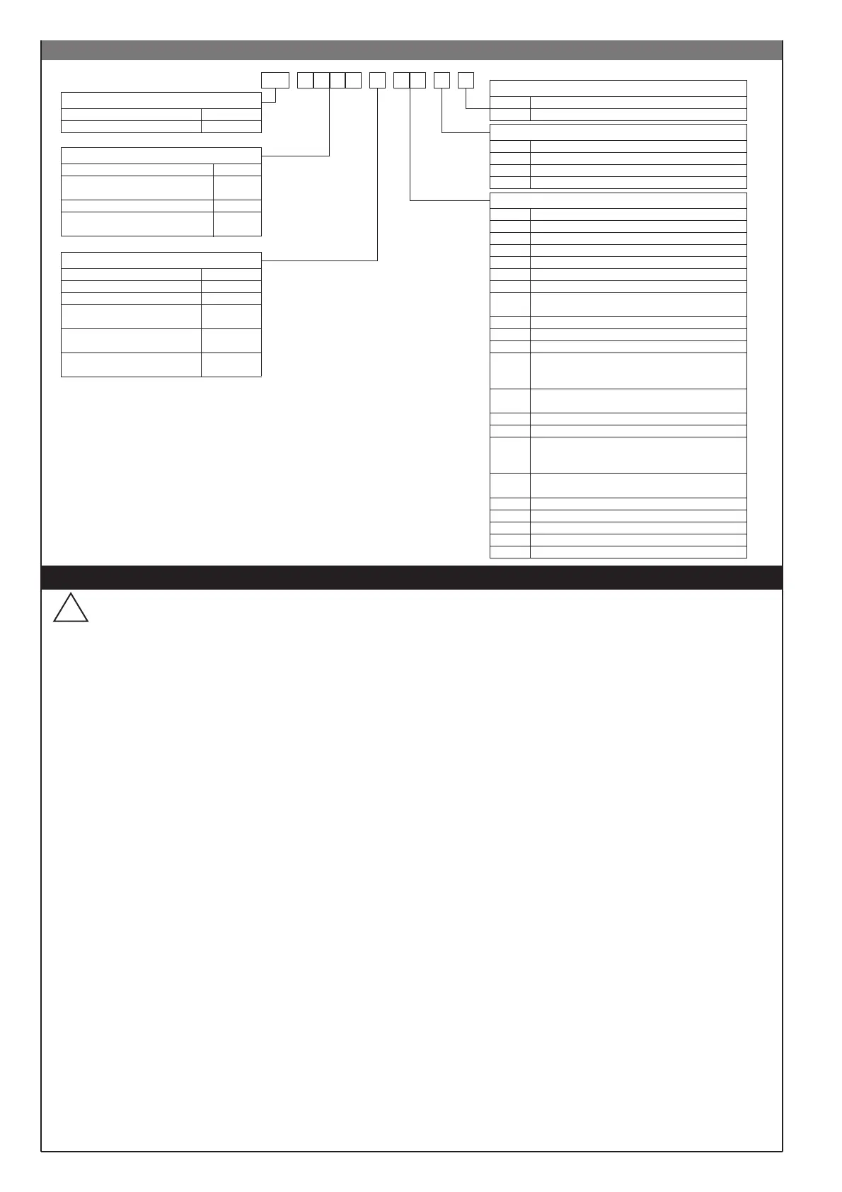
(*) Indicates the standard version
(**) Add +15 to obtain Transmitter Supply 24V
# Potentiometer input requires 10V transmitter
supply
For a PTC input a specific calibration has to
be requested
16
Before installation, please read the following advices:
• follow the indications of the manual scrupulously when making the connections to the instrument
• use a cable that is suitable for the ratings of voltage and current indicated in the technical specifications
• the instrument has no ON/OFF switch for the power, it operates immediately the supply is connected; for safety reasons, the devices permanently
connected to power supply require ON/OFF switch with proper warking; the switch must be close to the unit and should be easily reachable by the user. A
single switch can be connected to several units.
• if electrically NON-ISOLATED equipment is connected to the instrument (e.g. thermocouples), a ground wire must be connected to avoid that this
connection is made through the machine
• if the instrument is used in applications where there is risk of injury to persons and damage to machines or materials, it is essential that it is used with an
auxiliary alarm device. It is advisable to verify frequently that the alarm device is functional even during the normal operation of the equipment
• before using the instrument, it is the user's responsibility to ensure the correct instrument settings to avoid injury to persons or damage to objects and
materials
• the instrument must NOT be used in environments where there could be the presence of dangerous atmospheres (inflammable or explosive); if the
instrument is used with elements that operate in such atmospheres, they must be connected through an appropriate interface or safety barrier that
conforms to the local safety regulations in force
• the instrument contains components that are sensitive to static electrical discharges and appropriate precautions must be taken before handling the
electronic circuit boards if permanent damage to these components is to be prevented
Installation:
installation category II, pollution degree 2, double isolation
• the power supply wiring must be kept separate from that of inputs and outputs of the instrument; always check that the supply voltage corresponds to
that indicated on the instrument label
• install the instrumentation separately from the relays and power switching devices
• in the same cabinet, do not install power contactors,, contactors, relays; thyristor power units “particularly if phase angle”; motors, etc...
• keep away from dust, humidity, corrosive gases and heat sources
• do not close the ventilation holes; the working temperature must be in the range 0...50°C.
If the unit has faston terminals they must be of the protected and isolated type; if the unit has screw terminals it is necessary to fix the cable in pairs.
•
Power supply
: should be taken from an isolator with a fuse for the instrument section; the path of the supply wiring should be as direct as possible from
the isolator to the instruments: the same supply should not be used to power relays, contactors, solenoid valves, etc.; if the voltage waveform is strongly
distorted by thyristor switching units or by electric motors, it is recommended that an isolation transformer is used only for the instruments, connecting the
screen to ground; it is important the electrical plant has a good ground connection, the voltage between neutral and ground must not exceed 1V and the
resistance must be less than 6Ω; if the supply suffers large voltage swings, use a voltage stabiliser for the instrument supply; in the vicinity of high
frequency generators or arc welders, use line filters; the power supply wiring must be kept separate from the that of the inputs and that of the outputs of
the instruments; always check that the supply voltage corresponds to that indicated on the instrument label
•
Input and output connections:
for connecting analogue signals (TC, RTD) it is necessary to: physically separate the input wiring from that of the power
supply wiring, from the wiring to the outputs and from power connections; use twisted and screened cables, with the screen connected to ground at only
one point to use RC (resistor and capacitor in series) spark suppression components in parallel with inductive loads that operate in ac (contactors,
solenoid valves, motors, fans, etc.) connected to the outputs of the instrument (
Note: all the capacitors must conform to the VDE standard (class x2) and
withstand a voltage of at least 220Vac. The resistor must be at least 2W
); fit a diode 1N4007 in parallel with the coil of inductive loads that operate in dc
SPIRAX-SARCO srl will not be held responsible for injury to persons or damage to objects and materials caused by mishandling,
incorrect or erroneous use that is not in conformity with the instrument specifications.
!
WARNING: this symbol indicates danger.
You can see it close the power supply circuit and the relay contacts that may be connected to high voltage.
• WARNINGS
36 IN CT (50mAac)
16**
IN1, IN2 PNP
IN SPR (0/4...20mA) + Transmitter Supply 10V
17** IN1, IN2 PNP, IN CT (50mAac) + Transm. Sup. 10V
33 IN SPR (0...1V)
34 IN SPR (0...10V)
35 IN SPR (0/4...20mA)
15**
IN1, IN2 PNP
IN SPR (0...10V) / IN Potentiometer #
+ Transmitter Supply 10V
13** IN1, IN2 NPN, IN CT (50mAac) + Transm. Sup.10V
12**
IN1, IN2 NPN
IN SPR (0/4...20mA) + Transmitter Supply 10V
11**
IN1, IN2 NPN
IN SPR (0...10V) / IN Potentiometer #
+ Transmitter Supply 10V
POWER SUPPLY
20...27Vac/dc ±10%0
100...240Vac/dc ±10%1*
DIGITAL COMMUNICATIONS
None0*
Current Loop1
RS 4852
RS 232C3
05** IN1, IN2 PNP + Transmitter Supply 10V
ORDER CODE
AUXILIARY INPUTS
None
IN1, IN2 NPN
00*
01
IN1, IN2 PNP
Transmitter Supply 10V
02
03**
IN1, IN2 NPN + Transmitter Supply 10V04**
10** IN1, IN2 NPN, IN SPR (0...1V) + Transm. Sup. 10V
IN SPR (0...1V) + Transmitter Supply 10V
IN SPR (0...10V) / IN Potentiometer #
+ Transmitter Supply 10V
06**
07**
IN SPR (0/4...20mA) + Transmitter Supply 10V08**
IN CT (50mAac) + Transmitter Supply 10V09**
14** IN1, IN2 PNP, IN SPR (0...1V) + Transm. Sup. 10V
 Loading...