Do you have a question about the Spirax Sarco SX75 Series and is the answer not in the manual?
Precautions for safe installation, emphasizing qualified personnel and proper electrical practices.
Details on CE marking, EMC directives, and potential interference sources for safe operation.
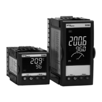
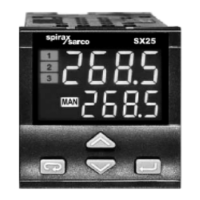
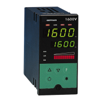
Description of the SX75 controller's features, capabilities, and types.
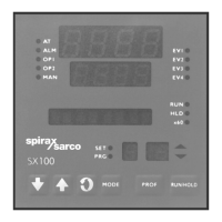
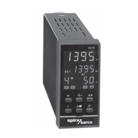
Explanation of the controller's numeric displays and their meanings in different modes.
Description of LED indicators related to the controller's output states (Y1, Y2, Y3).
Description of LED indicators for operating states like Manual, Remote, and Auto-Tune.
Detailed explanation of the function of each key on the controller's interface.
Technical drawings showing external dimensions and mounting requirements of the controller.
Step-by-step guide for installing the controller into a panel, including fitting and fixing methods.
Diagram and description of the controller's terminal board layout and connections.
Instructions on how to access and prepare the terminal connections for wiring.
Guidance on selecting and connecting wires, including terminal types and cable sizes.
Steps to properly secure and protect the terminal board after wiring.
General safety precautions to be observed during electrical wiring of the controller.
Recommended routing and layout for power supply and signal conductors.
Schematic representation of the controller's internal and external electrical connections.
Details on the controller's power supply requirements and specifications.
Configuration and connection details for the primary measuring input 'X'.
Wiring and specifications for connecting an external remote set point signal.
Description of how logic inputs are used for controlling operating modes and set points.
Wiring instructions for using a potentiometer to control valve motor drive position.
Guidance on using auxiliary relays to protect internal relays when driving VMD actuators.
Details on output options for main output Y1: relay, current, voltage, and logic.
Further details on Y1 output configurations: Valve motor drive, Dual action relay, Continuous dual action.
Description of event outputs Y2 and Y3, including wiring and specifications.
Details on the retransmission output Y4, its options, and configuration.
Information on serial communication interfaces (RS232/RS485) for the SX75+ model.
Procedure for accessing the controller's configuration using a password.
Procedure for accessing advanced parameters using a specific password.
Parameters related to setting and managing set points for the controller.
Parameters related to various functions and modes of the controller.
Advanced parameters and configuration options for specialized control.
Instructions for operating the controller during its normal running state.
Steps to retrieve previously stored set points from the controller's memory.
Guidance on switching between automatic and manual control modes.
Explanation of the auto-tune function for automatic parameter adjustment.
Configuration of event/alarm outputs based on deviation from set point.
Configuration of event/alarm outputs based on a defined band around the set point.
Configuration of event/alarm outputs based on the process variable range.
Event/alarm configuration with startup inhibition for deviation triggers.
Description of the loop-break alarm feature and its activation conditions.
Operating the controller using its front panel commands.
Controlling operating modes via external contacts connected to logic inputs.
Operating the controller remotely via serial communication.
Detailed table of how logic inputs change controller states or set points.
Specifications for the controller's measurement accuracy under different conditions.
Details of configurable input types and their specifications.
Information on the types and functions of auxiliary logic inputs.
Specifications for set point configuration, including ramps and limits.
Details on local and remote set point capabilities and their isolation.
Specifications for control algorithms (PID, Fuzzy) and action parameters.
Description of the automatic parameter adjustment (Auto-Tune) function.
Details on bumpless action and transfer between automatic and manual modes.
Technical specifications for main output Y1: relay, current, voltage, logic.
Technical specifications for event/alarm outputs Y2 and Y3.
Technical specifications for the retransmission output Y4.
Technical specifications for serial communication interfaces.
Details on parameter access levels and immunity to electrical disturbances.
Technical specifications for the standard and low voltage power supplies.
Specifications for the auxiliary power supply used for transmitters.
Ambient conditions, protection ratings, material, weight, and dimensions of the controller.
| Brand | Spirax Sarco |
|---|---|
| Model | SX75 Series |
| Category | Controller |
| Language | English |