Do you have a question about the Spirax Sarco BC3250 and is the answer not in the manual?
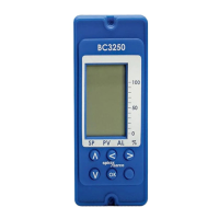
Accessing commissioning mode via the OK button for 5 seconds.
Ensure safe operation via proper installation, commissioning, use, and maintenance.
Product modifications or improper use can cause injury or damage, invalidating CE marking.
Product complies with EMC Directive 2014/30/EU for industrial environments.
Observe ESD precautions to prevent product damage from static discharge.
The BC3250 controls TDS by managing a blowdown valve and a timed bottom blowdown valve.
The controller manages alarm and set point levels for TDS/conductivity control of boiler water.
BC3250 accepts signals from conductivity probes and a Pt100 temperature sensor for measurement.
CCD system monitors condensate return conductivity, diverting flow to drain if contamination is detected.
Install the product in an environment that minimizes effects of heat, vibration, shock, and electrical interference.
Instructions for mounting the unit onto a 35 mm DIN rail using the provided clip and screws.
Essential precautions for safe electrical installation, including personnel qualification and compliance with standards.
Commissioning is performed via the front panel; normal control stops during this process.
Steps for altering parameters, including flashing digits and using navigation buttons.
Presents a flowchart of the main commissioning menu structure for program navigation.
Enables parameter passing between adjacent controllers via an infrared bus.
Explains RS485 addressing and offset for devices on an IR bus for network connectivity.
Use a damp cloth with tap/de-ionised water or isopropyl alcohol for cleaning.
Boiler blowdown controls and alarms require regular testing and inspection.
Weekly tasks include sampling water, checking calibration, blowdown valve, and stop valves.
Six-monthly tasks involve probe removal/cleaning and examination of valves and fittings.
Most faults occur during installation/commissioning; the Test menu aids troubleshooting.
Information on obtaining technical assistance from Spirax Sarco representatives or their website.
Guidelines for returning faulty equipment, including necessary information and packing advice.
Specifies the mains voltage range (110-240 Vac) and maximum power consumption (7.5 W).
Lists default settings for the MODE menu (OPEN or CLOSE).
Lists default settings for DATA menu units (Temp, TDS) and pH Term.
Lists default settings for INPUT menu: T COMP and TDS Sensor selection.
| Output | 4-20 mA |
|---|---|
| Enclosure | IP65 |
| Connections | Screw terminals |
| Application | Boiler control |
| Power supply | 50/60 Hz |
| Conductivity range | 0 - 10, 000 µS/cm |
| Temperature compensation | Automatic, 0-100°C |
| Alarm relays | 2 SPDT |
| Mounting | Panel mount |