33
5.6 Probe in blowdown (or condensate) line - CP10
For most applications the 1.25 m (4 ft) heat resisting probe cable will need to be extended
using a junction box. If not, link terminals 50 to 51, and 52 to 53.
Note: Whilst pairs of conductors are linked at the junction box, the four-wire connection is
required to compensate for voltage drop. See the Information and Maintenance Instructions
for the CP10 for further details.
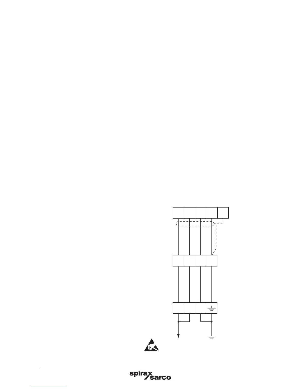
5.7 Probe in boiler - CP30
The probe requires a 4 core screened cable connection.
Whilst pairs of conductors are linked at the probe, the four-wire connection compensates for
voltage drop along the cable. The CP30 UL recognized probe is supplied with four 18 AWG,
12" long colour coded flying leads. These are to be cut to length and wired to a suitable
terminal block housed in a suitable metal box. A length of flexible metal conduit is required
between the probe and the terminal box to provide environmental and impact protection, and
easy electrical connection. The cable socket is provided with a ½" NPT conduit adaptor for
this purpose.
See the Information and Maintenance Instructions for the CP30 for further details.
5.8 Probe in boiler - CP32
The probe requires 8-way screened cable.See the Information and Maintenance Instructions
for the CP32 for further details.
Caution: Do not connect any wires
to the CP32 5-way terminal block,
as it houses the very fine wiring
from the probe, which could be
easily damaged in attempting to
connect additional wires.
5.9 TP20 Temperature
probe wiring
Note: For the TP20, when the cable
is to be longer than the 1.25 m (4 ft)
supplied, a junction box and 3 core-
screened cable will be needed.
Colour codes for sensor wires vary,
but a three-wire sensor will normally
have 2 wires of one colour, and 1 wire
of a different colour.
5.10 Four wire Pt100
Will have two wires one colour, and
two wires of another colour.
Link one of the pairs at the junction
box, and connect to terminal 56.
Connect one of the remaining two
wires to terminal 57, and the other to
terminal 58.
BC
controller
50 51 52 53
1 2 3
Terminal box
CP30 (UL)
connector
Probe tip
CP30 probe
Earthed to
probe body
Internal links
Red
Red
Black
Black
Fig. 25 Alternative wiring for the UL version
54