EasyManua.ls Logo

Spirotech SpiroVent Superior Series User Manual

Spirotech SpiroVent Superior Series
23 pages
To Next Page IconTo Next Page
Page #1 background imageLoading...
Page #1 background image
User manual - 1.0 English 2
EnglishUser manual
TABLE OF CONTENTS
/i
1PREFACE
1.1 About the device
This user manual describes the installation,
commissioning and operation of the following SpiroVent
Superior types:
/i
1.2 About this document
Read the instructions before installation, commissioning
and operation. Keep the instructions for future reference.
The original language of the document is English. All
other available language versions are translations of the
original instructions.
The illustrations in this document show a typical setup
with relevant details for instructional use only.
Differences between the illustrations and the device are
possible but do not have an effect on the
comprehensibility of this document.
All rights reserved. No part of this manual may be
duplicated and/or made public through the Internet, by
means of printing, photocopying, microfilm or in any
other way without prior written permission from
Spirotech bv.
This manual has been composed with the utmost care.
Should, however, this manual contain any inaccuracies,
Spirotech bv cannot be held responsible for this.
1.3 Symbols
Throughout the instructions the following symbols are
used:
1Preface 2
2 Introduction 3
3 Technical specifications 7
4Safety 7
5 Installation and commissioning 8
6Operation 13
7 Failures 17
8 Maintenance 20
9 Guarantee 23
10 CE statement 24
Type Article code Description
S600 MV06A.. Automatic vacuum degasser
S600-R MV06R.. Automatic vacuum degasser,
including integrated refill
function with direct refill
connection.
S600-B MV06B.. Automatic vacuum degasser,
including integrated refill
function with backflow
prevention.
Warning or important note
Note
Risk of electric shock
Risk of burning
Question and Answer IconNeed help?

Do you have a question about the Spirotech SpiroVent Superior Series and is the answer not in the manual?

Spirotech SpiroVent Superior Series Specifications

General IconGeneral
MaterialBrass
Maximum Pressure10 bar
Connection TypeThreaded
ApplicationHeating and cooling systems
TypeAir vent
Connection Size1/2", 3/4"

Summary

Preface

About the Device

Describes the installation, commissioning, and operation of SpiroVent Superior types.

About this Document

Instructions for installation, commissioning, and operation. Keep for future reference.

Symbols

Explains warning, note, risk of electric shock, and risk of burning symbols.

Introduction

Overview of the Unit

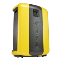
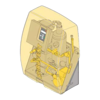
Details the components of the SpiroVent Superior unit with numbered diagrams.

Operation

Schematically shows unit operation with letter indications corresponding to figures.

Operating Conditions

Specifies unit suitability for clean water or glycol mixtures up to 40%.

Remote Monitoring

Discusses remote monitoring via BMS or Internet connection.

Scope of Delivery

Lists items included in the SpiroVent Superior package.

CE Marking

Confirms unit compliance with safety and health regulations.

Type Plate

Details information found on the unit's type plate.

Technical Specifications

General Specifications

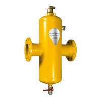
Lists general specifications like weight, noise level, and fluid connections for different models.

Operating Characteristics

Details operating parameters such as pressure, temperature, and refill flow rates.

Electrical Specifications

Outlines electrical requirements including supply voltage, protection, and fuses.

Dimensions

Provides physical dimensions (height, width, depth) of the unit.

Safety

Safety Instructions

Refers to a separate document for detailed safety instructions and information.

Installation and Commissioning

Installation Conditions

Specifies requirements for installing the unit in a frost-free, well-ventilated place.

Unpack

Provides instructions on how to safely unpack the unit.

Mounting and Installation

Details how to mount the unit and mechanical installation steps.

Commissioning

Guides through filling the unit and the first startup procedure.

Operation

HMI User Interface Description

Overview of the HMI, screen layout, buttons, indicators, and page navigation.

Unit State and Settings

Details unit states, configuration settings, and how to switch the unit on.

Operation Controls and Modes

Explains how to change settings, switch off the unit, and manage operating modes.

Refill Process and Remarks

Covers refill procedures, manual refill, and general operational notes.

Failures

Remedy Failures

Provides guidance on warning installers, removing power, and checking for leaks.

Replace a Fuse

Instructions for replacing fuses, including electrical specifications and error codes.

Taking Out of Operation

Steps to safely take the unit out of operation before repairs.

Resetting the Unit

Procedure for clearing fault messages and resetting the unit.

Failure Table

Lists problems, possible causes, and corrections for various unit failures.

Maintenance

Periodic Maintenance

Details routine checks like float valve inspection and air vent replacement.

Replacement Parts

Lists spare parts and their corresponding article numbers for the unit.

Maintenance Card

A template for recording inspection dates, technician details, and maintenance nature.

Guarantee

Terms of Guarantee

Specifies the guarantee period and conditions, excluding consequential damage.

CE Statement

EC Declaration of Conformity

Declares the unit's compliance with relevant European Directives and applied standards.

Related product manuals