This document is an original instruction manual for the JETFIRE J20A & J45A portable industrial heaters, manufactured for Spitwater Australia Pty Ltd. The manual provides comprehensive information on the operation, safety, and maintenance of these units.
Function Description
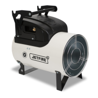
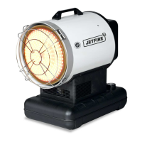
JETFIRE heaters are designed for industrial use, specifically for heating, drying, and desiccating in commercial and industrial applications. Examples include warehouse and factory heating, animal husbandry, and greenhouse applications. They are direct-combustion and forced convection units, meaning air is heated by thermal energy from combustion and then conveyed into the room along with combustion products. Therefore, the room must be adequately ventilated to ensure proper air circulation. The heaters are intended for space heating only and are not for domestic use.
Important Technical Specifications
The manual provides detailed technical data for both the J20A and J45A models:
The manufacturer reserves the right to modify designs, features, and technical data without notice.
Usage Features
The JETFIRE heaters are designed for safe, efficient, and reliable service when operated correctly. Key usage features and instructions include:
- Operation: The heater must be positioned and operated on flat, stable ground, in an upright position, and not exposed to the elements. It should only be used in a well-ventilated space.
- Gas Connection: The heaters use LPG and require connection to a gas cylinder. The manual specifies a minimum of one 45KG cylinder to minimize "freezing" effects, especially in low temperatures. All gas connections have left-hand threads and must be tightened anticlockwise. A gas hose and pressure reducer with fittings are supplied.
- Electrical Connection: The unit requires a 230/1/50 V/~/Hz electrical supply and must be connected to an earthed power supply with an appropriately sized fuse. It is recommended that the electrical supply include a residual current device (RCD) that interrupts the supply if leakage current exceeds 30mA for 30ms.
- Starting Procedure: To start, set the pressure regulator to maximum, slowly open the gas stopcock on the cylinder, ensure the heating switch (9) is set to "0", and turn on the switch on the main electrical panel. For models with or without a room thermostat, move the heating switch (9) to the appropriate position. The automatic starting cycle begins, and the reset button (8) flashes rapidly until the flame lights up.
- Stopping Procedure: To stop, turn the thermostat adjustment down (if connected), which extinguishes the flame and stops the fan motor. Close the gas supply stopcock and turn off the heating switch. If the heater is not used continuously, close the gas supply stopcock first, then switch it off or turn down the thermostat to allow residual gas in the tube to be used.
- Room Thermostat: The heater can be connected to a room thermostat (10) or other accessories like a timer.
- Safety Devices: The unit is equipped with a Temperature Limit Control/overheating thermostat (LI) to shut off the heater if internal temperature rises unsafely. The electrical system is protected by a fuse on the PCB. A Flame-Out Sensor causes the electronic burner control unit to trip if the flame is irregular or goes out, indicated by a steady red light on the reset button (8). The heater can only restart after the reset button (8) is pressed.
Maintenance Features
Regular inspection and maintenance are crucial for efficient operation and to prolong the heater's life. The manual outlines a maintenance schedule and procedures:
-
Maintenance Intervals (Table A):
- Every day: Check heater, check gas supply line (Owner)
- Every week: Clean exterior of heater, check electrical connections (Owner)
- Every 6 months: Clean motor & fan (Authorized service Agent)
- Every year: Clean burner & combustion chamber (Authorized service Agent)
- Note: These intervals are for normal operating conditions; abnormal conditions (e.g., constant use, extreme temperatures) require reduced intervals.
-
Pre-Maintenance Safety: Before any maintenance, stop the heater, switch off the power supply, and wait for the heater to cool.
-
Checking Heater and Gas Supply Line:
- Ensure the heater is not in a fire/explosion risk area and flammable materials are kept away.
- If gas is smelled, open windows, do not touch electrical switches, close gas stopcock, find and repair the leak.
- Ensure all panels are remounted and the room is ventilated.
- Ensure air intake/outlet are unobstructed and the heater is stable.
-
Cleaning Exterior: Clean pipes, connectors, joints, external body, and air inlet/outlet with a cloth. Remove dirt and debris from air inlet/outlet.
-
Checking Electrical Connections: After detaching the power cable, check all connections for completeness and tightness. Contact an authorized Spitwater service agent if dirt, corrosion, or damaged wires/connectors are found.
-
Cleaning Motor and Fan (Authorized Service Agent Only): Remove the fan safety grille, clean the motor and fan blades with a cloth or hard brush, then reinstall the grille and close the inspection panel.
-
Cleaning Combustion Chamber (Authorized Service Agent Only): This should be done at least once a season or more frequently if soot builds up. Access by removing the side inspection panel, clean with compressed air or a metal brush, then reinstall the safety grille.
-
Troubleshooting Guide: A detailed table helps identify causes and remedies for common faults such as the heater failing to start, flame issues, or fan noise.
-
Service Contact: For spare parts, accessories, and service, refer to www.spitwater.com.au or contact 1800 SPITWATER (1800 774 892).
Safety Warnings and Symbols
The manual emphasizes safety with various warning symbols:
- Exclamation Mark (!): Indicates a warning where failure to follow instructions could result in injury or death.
- Stop Sign: Indicates a warning where failure to follow instructions could result in damage to the machine.
- "i" in a circle: Provides tips and instructions for safe and proper operation.
- Hot Surface Symbol: Warns of hot surfaces that should not be touched to avoid injury.
- Electrical Shock Symbol: Warns to disconnect power before removing the cover to prevent electric shock.
- Gas Leak Symbol: Warns that propane is heavier than air, and gas leakage can cause stagnation on the floor.
- Trip Hazard Symbol: Warns of potential trip hazards from loose cords.
- Fire/Hot Surface Symbol: Warns of fire prevention and hot surface caution.
- Exhaust Fumes Symbol: Warns that exhaust fumes (carbon monoxide) can be deadly if allowed to build up.
The manual stresses that all operators must read and understand the information and instructions, and be aware of possible hazards. Failure to follow instructions releases Spitwater Australia from responsibility and may void the warranty. Only persons instructed and authorized should operate the heater. Safety labels must not be altered or removed.