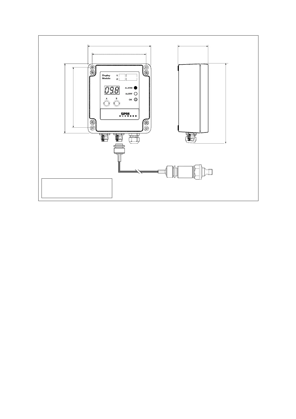
Installation of Bearing Display Module BDM
2
Technical data for Bearing Display Module BDM-40 and BDM-42
Measuring method: SPM dBm, unnormalized maximum value
Measuring channels: 2, multiplexing
Measuring range 1: 0 to 80 dBsv (5 dB /mA, 0.2mA/dB)
Measuring range 2: 20 to 100 dBsv (4 mA ≤ 20 dBsv)
Measuring time: approx. 1 second per channel
Transducer type: SPM 40000 (BDM-40), SPM 42000 (BDM-42)
Transducer cable: coaxial cable, SPM 90005-L, or 90267-L (L = length in m)
Analog output: 4 to 20 mA, no galvanic separation
Fault indication: ≤1 mA out = interrupted or faulty transducer line
Loop resistance: max. 450 Ω at 12 V, 1.1 kΩ at 24 V
Power supply: 12 to 24V DC (± 10%, tested according to EN 50082-2) source
referred to earth
Supply current: max. 0.15 A
Cable inlet: IP 65 at ø 5.5 to 10 mm
Housing: polycarbonate, IP65
Temperature range: 0 to 55 °C
Vibration exposure: max. 5 mm/s RMS
Dimensions: 110 x 149 x 56 mm
Mounting screws: 4 screws, ø 4 mm, spacing 109 x 94 mm
Weight: 400 g
Signal to display: 4 to 20 mA, 2 channels
Relays: 2, max. 24 V/100 mA
Value display: 3 digits LED
Condition display: green, yellow, and red LED
Alarm limits: 2 per input channel, set with push-buttons
Push-buttons: 2, for display control and settings
56
124
110
109
94
149
Coaxial cable with
TNC connectors
Shock pulse transducer
Module Transducer Cable length
BDM-40 40000 max. 4 m
BDM-42 42000 max. 100 m
 Loading...