Installation of Bearing Display Module BDM
6
No. Quantity Unit 4mA 20mA
00 Test 0-20 mA mA 4.0 20.0
01 Vibration mm/s 0.0 5.0
02 Vibration mm/s 0.0 10.0
03 Vibration mm/s 0.0 20.0
04 Vibration mm/s 0.0 40.0
05 Shock pulse dBsv 0 80
06 Shock pulse dBsv 20 100
07 Temperature °C -16 120
08 Vibration inch/s 0.00 0.19
09 Vibration inch/s 0.0 0.39
10 Vibration inch/s 0.0 0.78
No. Quantity Unit 4mA 20mA
11 Vibration inch/s 0.0 1.57
12 Temperature °F3248
13 Percentage % 0 100
14
15
16
17
18
19
20
( Free configuration of programs 14 - 20 )
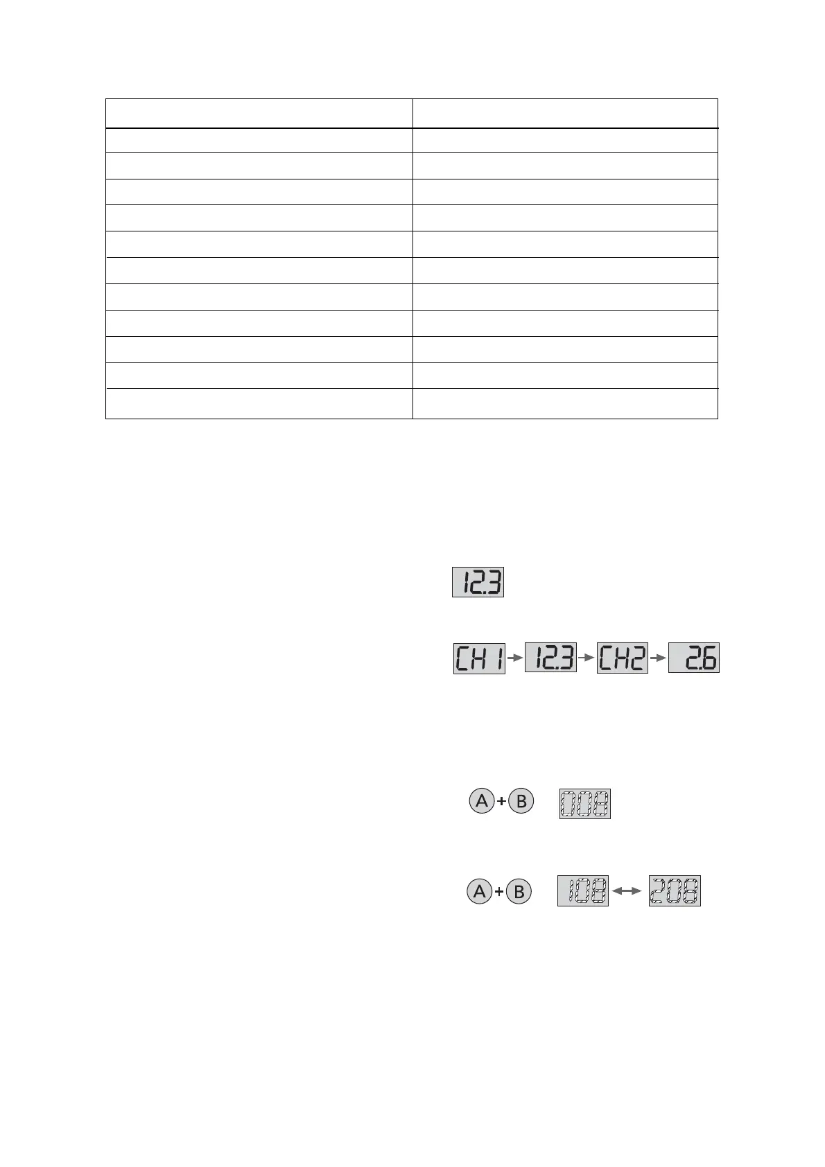
Display during operation
In 'one channel mode', the number display shows the
value on channel 1. The LEDs show the status:
Level 2 ALARM red
Level 1 ALERT yellow
Signal < 4 mA flashing yellow (not program 00)
OK green.
Channel and active program
3 seconds
One channel mode
Two channel mode
Active program
3 seconds
One channel mode
Two channel mode
To check the active program(s), hold down A+B until all
LEDs light up and the number display flashes. The display
shows one digit for measuring mode/channel followed by
two digits for the active program:
0XX One channel mode, program no. XX
1XX Two channel mode, program no. XX on channel 1
2XX Two channel mode, program no. XX on channel 2.
The module returns to the measuring mode after 30
seconds.
The 'one channel mode' can be programmed for channel 1 even when both channels are receiving input
signals. In this case, no results for channel 2 will be shown until the mode is changed. It is not possible to
measure on channel 2 only. If channel 1 is disconnected while the module is active, there will be a
continuous 'interrupted circuit' status (flashing yellow LED, outgoing analog signal ≈ 0 mA). Please note
that this does not apply to program 00, which is a test function showing the actual input current.
If an alarm delay cycle is interrupted by a measured value below the alarm limit, it starts again from 0
when the next value above the alarm limit is received.
Measuring programs
Programs 05 (0 – 80 dBsv) and 06 (20 – 100 dBsv) are used for shock pulse measuring and should
correspond to the measuring range set by the jumper on the lower measuring circuit board.
In 'two channel mode', the display alternates between the channels, showing CH1 – value, then CH2 –
value. The alarm status for the active channel is shown by the LEDs as in 'one channel mode'.

 Loading...