3
Installation of Bearing Display Module BDM
The analog signals 4 - 20 mA can also be used in
the AMS unit for on-line condition monitoring in
connection with the SPM Condmaster
®
Pro soft-
ware.
Note that the max. total loop resistance of a 4-
20 mA circuit depends on the signal source. As a
rule, loop resistance should not exceed 400 Ω in
a CMM system.
Loop resistance R = 47 + 47 + 75 = 169 Ω
+ cable resistance. Maximum 400 Ω
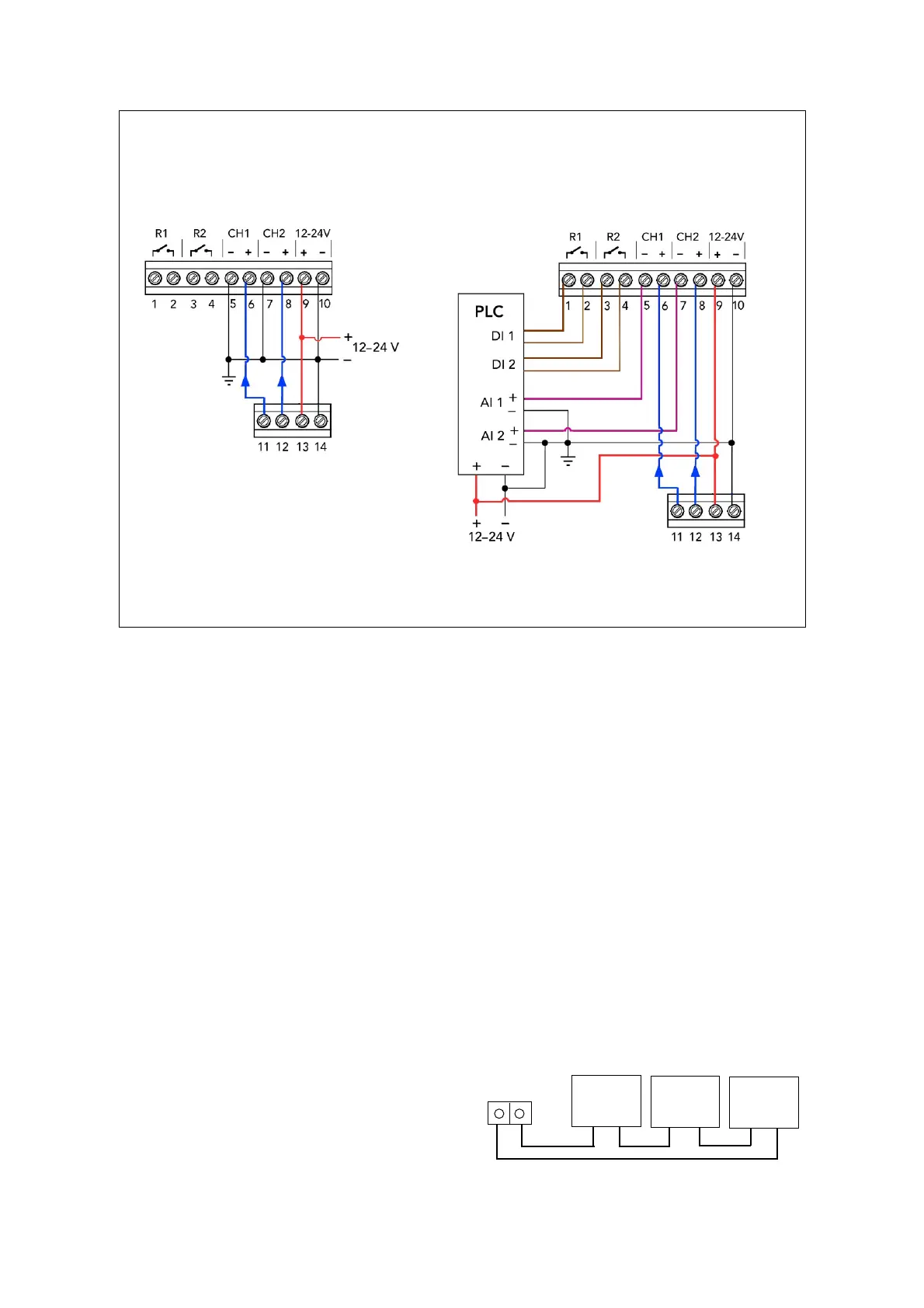
Electrical installation
When used as a stand-alone display unit, the module is connected to a 12 - 24 V DC power source with
earth reference. All electric connections are made to the upper circuit board. The jumpers connecting
the analog channels to earth are factory mounted and can be removed when connecting to a PLC.
BDM modules are delivered with jumpers that connect the 4 - 20 mA output of the lower measuring
circuit to the upper display circuit.
When connected to a PLC, the display module can get its power supply from it. The jumpers from the
analog channels are removed. The analog channels are connected to the PLC's AI (analog in) unit, the
relays to the DI (digital in) unit.
Please note: The return line from the current loop are connected to the negative pole on the power
supply.
Mechanical installation
The module is wall mounted, with 4 screws through the back of the casing. The screw diameter is 4 mm, the
spacing is 109 x 94 mm. The module housing has a transparent lid fixed to the box by four screws and has
to be opened for installation and programming. The maximum vibration exposure is 5 mm/s RMS. The
temperature range is 0 to 55 °C (32 - 130 °F). The incoming signal/power cables must have a diameter of 5.5
to 10 mm to maintain IP65.
Analog
signal
– +
PLC
75 Ω
+ –
AMS
47 Ω
+ –
BDM
47 Ω
+ –
4–20 mA
BDM connected to PLC
measuring circuit board
(lower)
BDM
measuring circuit board
(lower)
 Loading...