Installation of Bearing Display Module BDM
4
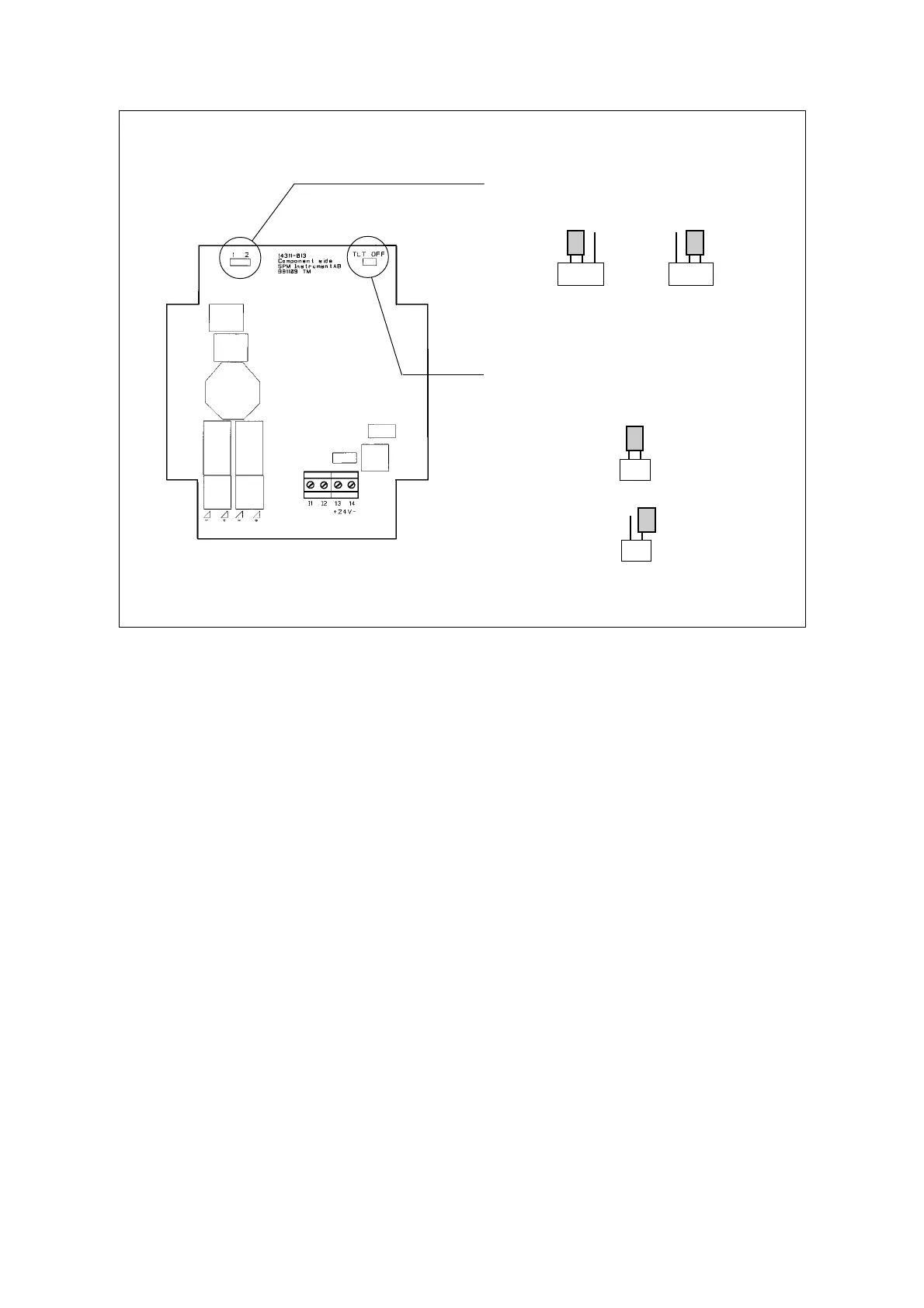
Measuring
circuit board
BDM modules contain two circuit boards, the bearing measuring circuit board (lower) and the display
circuit board (upper) for 4 – 20 mA analog signals. The analog output(s) on the measuring board are
factory connected to the display board.
All electric connections are made to the upper display circuit board. The lower board has two jumpers,
one is used to select the measuring range and one to select TLT OFF (this jumper is factory mounted on
one of the contact pins).
Measuring range setting
The jumper socket marked 1 2 in the upper left corner on the circuit board is used to set the measuring
range in unnormalized shock values:
1. 0 – 80 dBsv 2. 20 – 100 dBsv
One of these ranges must be selected and have effect on both channels. The factory setting is 0 - 80 dBsv.
The range can be changed at any time. Note that the display range program or the PLC must be changed
accordingly.
TLT OFF (test)
In case of transducer line fault (open or short circuit), the analog signal goes down to <1 mA. To avoid
problems with e.g. a PLC, one can move the jumper to both contact pins at ”TLT OFF” on the circuit
board. This will eliminate the transducer line test and keeps the channel output at min. 4 mA in case of
fault.
0 – 80 dBsv 20 – 100 dBsv
TLT OFF (test)
12
12
A jumper can be set at TLT OFF for test
(min. 4 mA in case of TLT fault)
TLT (normal)
Jumper for setting of measuring range