November 1999 / BULLETIN 90-21-1
EVAPORATOR PRESSURE
REGULATING VALVES
Installation & Service Instructions
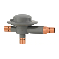
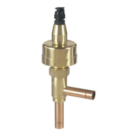
(S)ORIT-12
(S)ORIT-15
(S)ORIT-20
FOR USE ON REFRIGERATION and/or AIR CONDITIONING SYSTEMS ONLY
Bulletin 90-21-1, November 1999, supersedes Bulletin 90-21-1, dated October 1995, and all prior publications.
©COPYRIGHT 1999 BY SPORLAN VALVE COMPANY, WASHINGTON, MISSOURI
To insure optimum performance, evaporator pressure regu-
lating valves must be selected and applied correctly. This is
covered thoroughly in Bulletin 90-20-1. However, proper
installation procedures are equally important. All of the
information in the Application Section should be reviewed
before installing (S)ORIT valves.
VALVE LOCATION – The (S)ORIT-12, -15 and -20 must be
installed upstream of any other suction line controls or
accessories. They may be installed in the horizontal or verti-
cal position (Do not install upside down.) . . . whichever best
suits the application and permits easy adjustment and
accessibility. However, consideration should be given to
locating these valves so they don't act as an oil trap, or so
solder cannot run into the internal parts during brazing in
the suction line. Reverse flow is not recommended.
Therefore, a high side to low side hot gas defrost line must
be connected upstream of the (S)ORIT-12, -15 and -20.
INSTALLATION and BRAZING PROCEDURES — It is
not necessary to disassemble the valve when soldering to the
connecting lines. Any of the commonly used types of solder
(such as 50-50, 95-5, Easy-Flo, Phos-Copper or equivalents)
are satisfactory. It is important — regardless of the solder
used — to direct the flame away from the valve body and
avoid excessive heat on the diaphragm of the pilot valve. As
an extra precaution, a damp cloth may be wrapped around
the diaphragm during the soldering operation.
IMPORTANT: The pilot valve high pressure source is the
primary valve port closing force, so this connection must be
made for proper performance. There are several precautions
to observe when making this connection.
1. Generally the high pressure connection is made either to
the discharge line or the top of the receiver. If hot dis-
charge gas is used for defrost, the (S)ORIT pilot supply
line must originate from the same location as that of the
hot gas defrost line. The liquid line may also be used for
the high pressure connection. However, equipment man-
ufacturers sometime select other locations that are com-
patible with their specific design requirements.
Precautions should always be taken so this line does not
serve as an oil trap.
The pilot supply line should be kept as short as possible to
minimize condensing. Alternate feeding of gas and liquid to
the pilot supply may cause the valve to operate erratically.
2. It is also recommended that a hand valve or solenoid
valve (Sporlan A3) be installed in this line so the pilot
can be isolated should servicing become necessary. The
hand valve or solenoid valve is mandatory if it is neces-
sary to pump out an evaporator for service or for a pump-
down system. Closing the hand valve or solenoid valve
will cause the main piston to shift to the full open posi-
tion for rapid evacuation of the evaporator. The positive
closure of the pilot supply line is also necessary on pump-
down systems to eliminate the high side to low side
equalization path.
The (S)ORIT-12, -15 and -20 are normally open and by
closing off the pilot supply pressure (closing pressure), the
(S)ORIT main piston will shift to the full open position.
3. To insure proper performance, the high pressure source
supplied to the inlet of the pilot valve must be at least 50
psi above the outlet suction pressure of the (S)ORIT
evaporator pressure regulator.
TEST PRESSURES and DEHYDRATION TEMPERA-
TURES — For better leak detection, an inert dry gas, such
as nitrogen or CO
2
, may be added to an idle system.
CAUTION: Inert gases must be added to the system care-
fully through a pressure regulator. Unregulated gas pres-
sure can seriously damage the system and endanger human
life. Never use oxygen or explosive gases.
Excessive pressure can shorten the life of the pilot regu-
lator valve diaphragm. The maximum low side test pres-
sure that can safely be applied is 450 psig. This maximum
pressure is well above the minimum field leak test pres-
sures for low side listed in the ANSI/ASHRAE Standard
15-1994.
The maximum dehydration temperature the valve body can
be subjected without danger is 250°F.
VALVE SETTING and ADJUSTMENT — The standard
factory setting for the 0/100 psig range is 30 psig. The main
function of an (S)ORIT valve is to keep the evaporator pres-
sure above some given point at minimum load conditions.
Therefore, even though the valves are selected on the basis
of pressure drop at full load conditions, they should be
adjusted to maintain the minimum allowable evaporator
pressure under the actual minimum load conditions.
When adjusting both evaporator pressure regulating valves
and thermostatic expansion valves, the following procedure
is recommended.
®
INSTALLATION INSTRUCTIONS
ORIT
(S)ORIT