Do you have a question about the SportRack SR2901 and is the answer not in the manual?
Attaching part E to the main frame, and securing with part P.
Using parts K and M to secure the rack, with part P for adjustment.
Connecting bike support arms (C & D) to the main frame using part H.
Connecting arms (C & D) and frame supports (J) with part H.
Securing brackets (G) and arms (C & D) to the frame using part J and H.
Finalizing attachment of arms (C & D) and supports (P) with brackets (G) and frame piece (H).
Adjusting height of supports (C, D, P) using parts H and G, noting 'Small' and 'Large' positions.
Attaching the primary bike hooks (A & B) using part J.
Securing the primary bike hooks (A & B) with bracket G and part J.
Installing the hook arms (A and B) onto the main support structure.
Securing the installed hook arms (A and B) to the rack.
Finalizing the placement and securing of hook arms (A and B).
Attaching the hook arms (A and B) to the rack structure.
Final securing of the hook arms (A and B) to the rack.
Connecting frame part E with washer N and bolt I, and part L.
Detail of connecting frame part E with bolt I, washer N, and part L.
Inserting the hitch bar (F) into the frame mount (E), noting 2" receiver.
Securing the hitch bar (F) to the frame mount (E) using parts I, L, and N.
Tightening the hitch bar connection using a 3/4" wrench.
Finalizing the hitch connection with bolt I and pin O.
Preparing the hitch mount for attachment to the vehicle.
Attaching the hitch mount to the vehicle receiver using parts L and a pin.
Securing a rack arm component with a locking mechanism.
Securing multiple rack arms using locking pins.
Engaging a locking mechanism to secure components.
Final step to secure the rack assembly using a locking pin.
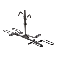
Illustration showing how to place bicycles onto the rack.
Ensuring hooks are well supported on bicycles and tightening handles.
Specific guidance for loading bicycles, especially women's bikes.
Always position the smaller bicycle between the bicycle support and the car bumper using the large hook.
Position hook in the cavity, between the vertical tube and the inclined tube of the bicycle.
| Brand | SportRack |
|---|---|
| Model | SR2901 |
| Category | Automobile Accessories |
| Language | English |