HACK ATTACK™ BASEBALL PITCHING MACHINE
SPORTS ATTACK, LLC. • 800-717-4251 • sportsattack.com
12
COMPONENT REPLACEMENT (cont’d)
CONTROLLER REPLACEMENT
1. Turn the on/off switch “OFF” and unplug the power cord.
2. Remove four screws holding controller faceplate into main casting. Note the position of
the main power and motor wires on the controller, then disconnect the wires. See Figure
10 on page 12 for the three motor wires. See Figure 11 on page 12 for the main power
cord wires.
3. Loosen the nuts holding the three speed control shafts to the faceplate, then remove
the controller.
Reassemble in reverse order.
Be sure wires are correctly reinstalled. Motor wire connectors are different sizes. Be
sure they are installed on the correct size terminal. See Figure 10 for the motor wires
and Figure 11 for the power cord wire.
Component Replacement
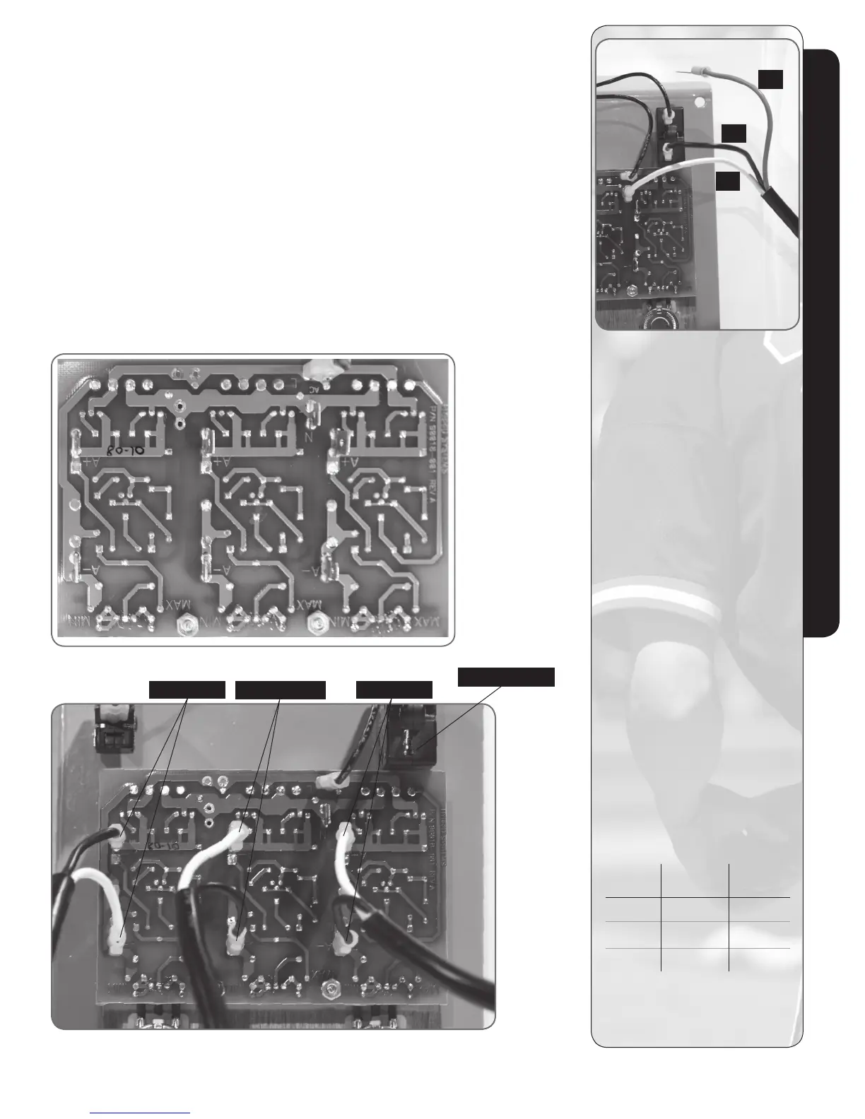
Figure 9 Wiring diagram from the control board side.
Figure 10
Wiring diagram for all three motors.
Right Motor
Circuit Breaker
Bottom Motor
Left Motor
CONNECTING WIRES
Motor Black White
Wire Wire
Right A- A+
Left A+ A-
Bottom A- A+
Black motor wires are
3
/
16
” female
disconnect and white wires are
1
/
4
” female disconnect.
#3
#1
#2
Figure 11
WIRING
POWER CORD
White or Blue Wire (1)
To middle male terminal marked “N.”
Black or Brown Wire (2)
To circuit breaker.
Green Wire (3)
Grounds to machine/motor.
MOTOR WIRE LEADS
Black 3/16” wide connectors.
White 1/4” wide connectors.
Black Wire (2) connects to A-
on circuit board.
White Wire (2) connects to A+
on circuit board.
CONTROLLER
Black Wire (2) 2 PR jumper wire:
- 1 from on/off switch to
circuit breaker
- 1 from on/off switch to
circuit board terminal “L”.