25
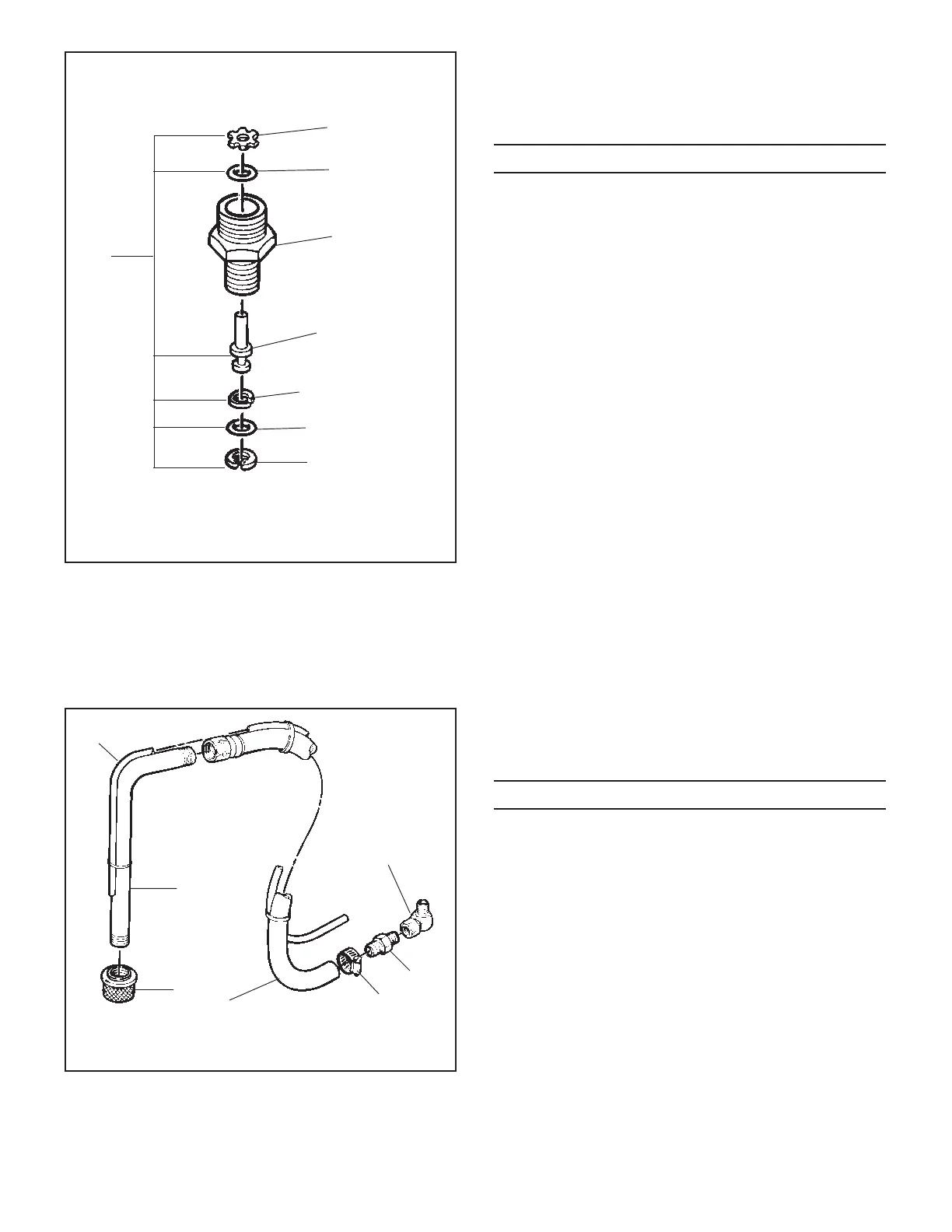
Figure 22 - Transducer Assembly
TRANSDUCER ASSEMBLY -
FIGURE 22
3
2
1
4
5
6
7
8
0294185 SUCTION SET
ASSEMBLY - FIGURE 23
ITEM PART NO. DESCRIPTION QTY
1 0090447 Elbow 1
2 13455 Fitting, Hose 1
3 53635 Clamp, Hose 1
4 0294426 Hose, Siphon 1
5 02975 Strainer 1
6 13463 Tube, Siphon 1
7 0294424 Hose, Return 1
Figure 23 - Suction Set Assembly
7
6
5
43
2
1
ITEM PART NO. DESCRIPTION QTY
1 50431 Retainer ring 1
2 50504 O-ring 1
3 02216 Transducer body 1
4 02232 Piston 1
5 50512 Back-up ring 1
6 50482 O-ring - Standard material 1
02305* O-Ring - Lacquer based
material 1
7 50423 Retainer ring 1
8 02283 Transducer Packing Kit
Includes Items 1, 2, and 4 through 7.
* Optional - for lacquer based material
NOTE: When paint begins to leak through the
weep hole on the transducer assembly, repack the
transducer assembly.