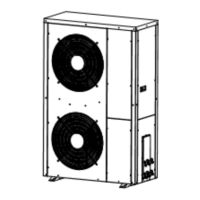
I
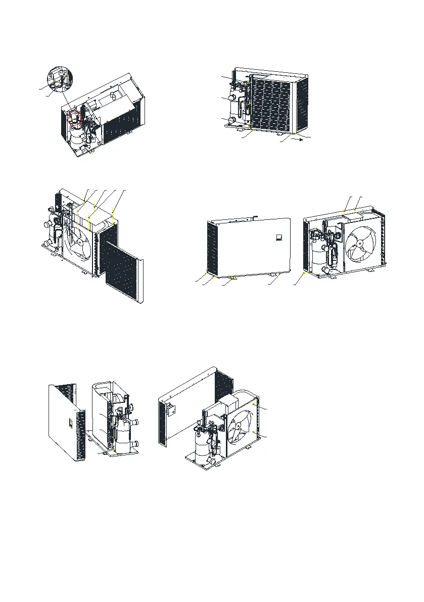
Step 7: remove the 23-24 screws at
the position shown in the figure to
take out the control panel
Step 8: remove the screws 25-26-27-28-29-30 at the
position shown in the figure, and then remove the
rear air outlet net
Step 9: remove the screws
31-32-33-34-35 at the position shown in
the figure to remove the evaporator
cover plate,The fan can also be checked at
this time
Step 10: remove the screws 36-37-38-39-40-41-42 at the
position shown in the figure to remove the front panel
Step 11: remove the screws 43-44-45-46-47 at the position shown in the figure to disassemble the
finned evaporator
24
23
Detail I
25
26
27
28
29
30
31
32
33 34 35
42
41
36
37
38
39
40
43
44
45
47
46


 To Next Page