52 | INSTALLATION, OPERATION and MAINTENANCE MANUAL
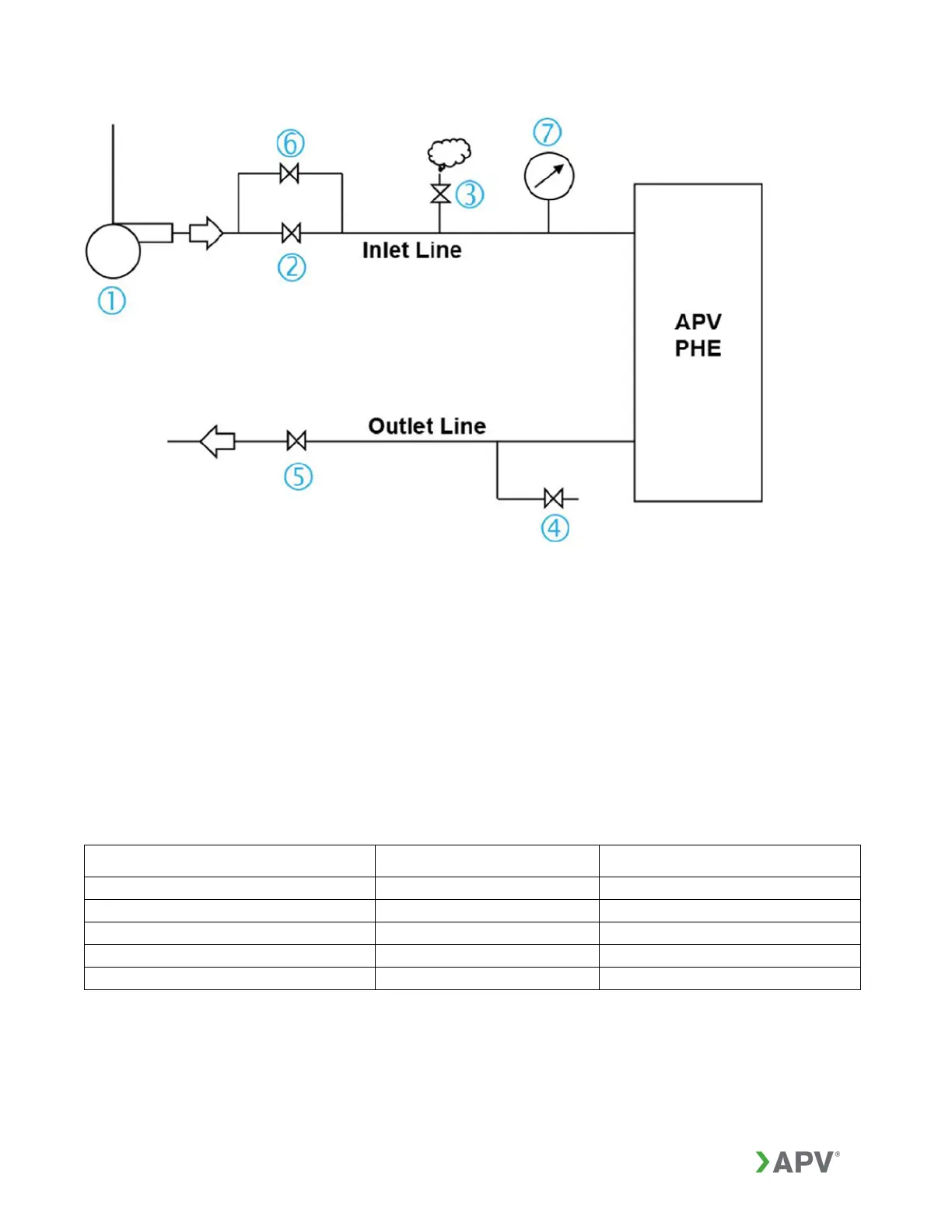
Figure 43: Typical liquid / liquid system configuration components
1. Pump, centrifugal
2. Inlet valve
3. Vent valve (always on top line)
4. Drain valve
5. Outlet valve for isolation
6. Bypass valve
7. Pressure gauge at inlet of the GPHE
Acceptable startup and shutdown procedure for the configuration in Figure 43:
Before startup, check that these conditions are met.
VALVE COLD MEDIUM HOT MEDIUM
Inlet valve (2) Closed Closed
Outlet valve (5) Open Open
Drain valve (4) Closed Closed
Vent valve (3) Partly open Partly open
Bypass valve (6), if fitted Open Open