70 | INSTALLATION, OPERATION and MAINTENANCE MANUAL
width. The drip tray is installed underneath the plate pack, elevated above the floor, and
typically slopes at a small angle towards the head. A drain is attached at the head end
of the drip tray to permit collection of media collected by the drip tray. Each
manufacturing site may have a unique method of attaching the drip tray to the plate heat
exchanger. The next two paragraphs provide examples of drip tray installation methods.
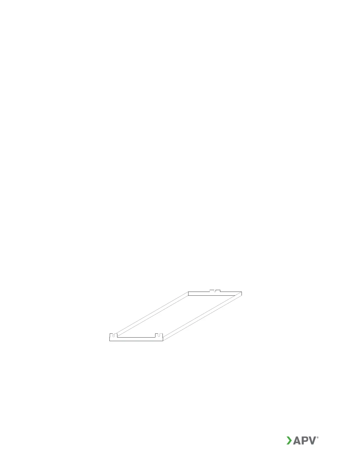
The drip tray in Figure 52 is attached to the inside of the head at the foot bolt
locations and inside of the end support at the foot bolt location. The drip tray in
Figure 53 is attached to the bottom side tie bars. These two types of drip pans
may be installed on the floor by extending the bolting tabs in Figure 52 or clamp
lengths in Figure 53.
A drip tray can be installed when the APV GPHE is insulated (see Section 13.6).
The drip tray (Figure 54) has support blocks attached to the bottom surface of
the drip tray and these blocks are attached beneath the plate heat exchanger
feet with the drip tray resting on the floor. The insulation will enclose the plate
heat exchanger and the drip tray. An opening in the insulation provides access
to the drain.
13.6. Insulation Jacket
The insulation jacket is designed to enclose the plate heat exchanger with a “suitcase
type” hook and latch system to attach the panels (Figures 55 and 56). The panels form
a box structure that is open at the bottom. The insulation jacket is not designed to fully
seal the plate pack, thus reducing the risk of unwanted build-ups.
The insulation jacket provides a safe temperature exterior surface when the plate
exchanger is operating at hot / high temperature and protects personnel from injury in
the event of a high temperature liquid discharge.
Figure 52: Drip tray