5
8
1
5C 5D
8
7
2
6
1
5A
10A
9A
3A
3B
9B
10B
5B
11
INLET
FIGURE 1A
88
5C
5D
7
2
6
1
1
5A
5B
11
10A
9A
3A
10B
9B
3B
INLET
LEGEND
Process Stream
Purge Stream
TOWER 4A DRYING: TOWER 4B REGENERATING
FIGURE 1C
7. Purge Orifice
8. Pressure Relief Valves
9. Purge / Repressurization Valves
10. Purge Mufflers
11. Moisture Indicator
1. Pressure Gauges
2. Purge Pressure Gauge
3. Inlet Switching Valves
4. Desiccant Drying Towers
5. Check Valves
6. Adjustable Purge Rate Valve
FIGURE 1B
TOWER 4B DRYING: TOWER 4A REGENERATING
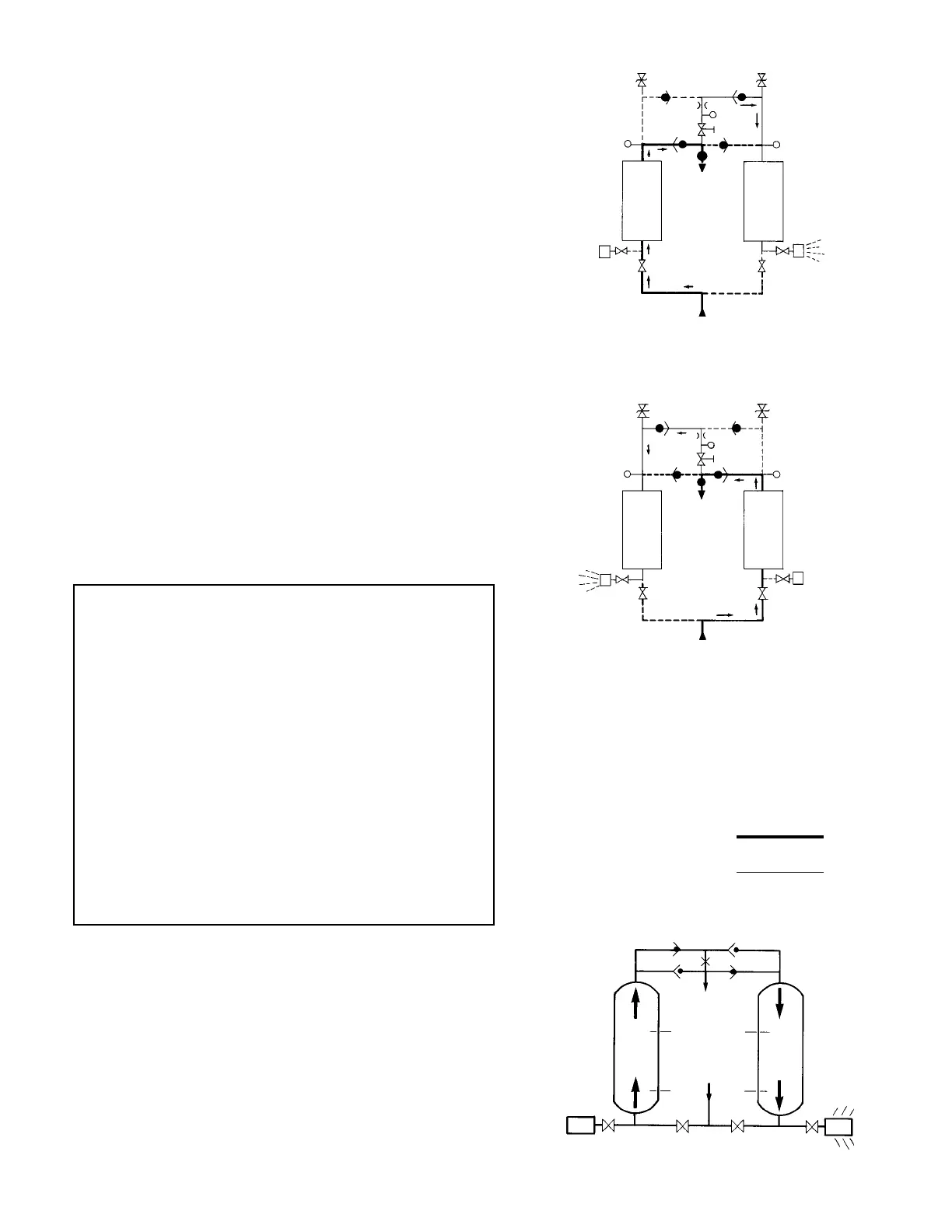
1.2 Description of Operation
1.2.1 Dryer
(Refer to Figure 1A.)
Compressed air flows through inlet switching valve (3A) to tower
(4A) where the air is dried. After the air is dried it flows through check
valve (5A) and then to the dryer outlet.
A portion of the dry air, the purge stream, branches off from the
main air stream prior to the outlet. The purge stream flow rate is controlled
by the adjustable purge rate valve (6) and the purge orifice (7).
The purge flow, which has been throttled to near atmospheric
pressure, is directed through check valve (5D) to tower (4B). As the purge
flow passes over the desiccant in tower (4B), it removes the water vapor
which was deposited there while the tower was on-line drying. The purge
air then passes through purge and repressurization valve (9B) and purge
muffler (10B) to the atmosphere.
After regeneration, purge and repressurization valve (9B) closes
allowing tower (4B) to repressurize slowly. Adequate repressurization time
is allowed so that tower 4B is fully repressurized before switchover. After a
controlled time period, air inlet switching valve (3B) opens and inlet
switching valve (3A) closes, purge and repressurization valve (9A) then
opens.
(Refer to Figure 1B.)
Tower (4B) is now drying the main air
stream while tower (4A) is being regenerated by the purge air stream. The
operation of the inlet switching and purge and repressurization valves is
sequenced by the control system located in the electrical box.
1.2.2 Optional Automatic Purge Saving System (Refer to Figure 1C)
Assume Tower A is on-line drying the air while tower B has just
gone off-line to be regenerated. At the beginning of tower B’s regenera-
tion cycle a temperature measurement is made at position B1. After the
tower has been regenerated, another measurement is made at B1. The
drop in temperature sensed during regeneration is an indirect measure
of the water vapor content of the inlet air. The Purge Saving System’s
microprocessor then uses this information to calculate an allowable
temperature rise in the bed during the drying cycle.
When tower B goes back on-line, a temperature probe at
position B2 measures the initial bed temperature at this point and then
monitors the bed until the calculated temperature rise occurs. The
temperature rise occurs as heat of adsorption is released during the
drying process. The time for the temperature rise to occur depends on
flow rate. At 100% flow the temperature rise takes five minutes, at 50%
flow it takes 10 minutes.
When the calculated temperature rise is reached, the towers
switch with tower A now drying and tower B being regenerated. Tower B
regenerates for 3.9 minutes, repressurizes, and remains idle until it is
called upon for the next drying cycle.
TOWER
4B
TOWER
4A
OUTLET
OUTLET
TOWER
4A
TOWER
4B
OUTLET
INLET
A2
B2
TOWER
A
TOWER
B
B1
A1
 Loading...