EasyManua.ls Logo

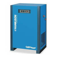
SPX Hankison HPRP Series User Manual

SPX Hankison HPRP Series
24 pages
To Next Page IconTo Next Page
Page #1 background imageLoading...
Page #1 background image
1
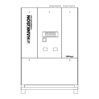
HPRP Series
Refrigerated Type Compressed Air Dryers
Models: HPRP100, HPRP125, HPRP150, HPRP200, HPRP250, HPRP300, HPRP400, HPRP500, HPRP600, HPRP750
FORM NO.: 5002730 REVISION: 01/2012 READ AND UNDERSTAND THIS MANUAL PRIOR TO OPERATING OR SERVICING THIS PRODUCT.
INSTRUCTION MANUAL

Questions and Answers:

SPX Hankison HPRP Series Specifications

General IconGeneral
BrandSPX
ModelHankison HPRP Series
CategoryDehumidifier
LanguageEnglish

Summary

GENERAL SAFETY INFORMATION

PRESSURIZED DEVICES

Safety precautions for pressurized components within the equipment.

ELECTRICAL SAFETY

Essential electrical safety requirements for operation and maintenance.

BREATHING AIR QUALITY

Advises on air suitability for breathing and necessary standards.

RECEIVING, MOVING, AND UNPACKING

RECEIVING SHIPMENTS

Instructions for inspecting shipments for visible loss or damage upon delivery.

UNPACKING AND CONCEALED DAMAGE

Guidance on checking for concealed loss or damage after unpacking.

MOVING THE DRYER

Important note on handling the dryer during transport to avoid tipping.

STORAGE AND SHUT DOWN

Precautions for storing the dryer and draining water-cooled units.

INSTALLATION PROCEDURES

LOCATION SELECTION

Guidance on selecting an appropriate location for dryer installation.

MOUNTING THE DRYER

PIPING CONNECTIONS

AIR INLET CONNECTION

Connecting the compressed air line to the dryer's air inlet.

AIR OUTLET CONNECTION

Connecting the dryer's air outlet to downstream air lines.

BYPASS PIPING INSTALLATION

Information on installing bypass piping for servicing without interrupting supply.

WATER COOLED MODELS CONNECTIONS

Details on connecting cooling water supply and return lines.

ELECTRICAL CONNECTIONS

VOLTAGE AND FREQUENCY MATCHING

Ensuring dryer operation matches voltage, phase, and frequency on the serial tag.

CORD AND PLUG INSTALLATION

Instructions for installing dryers supplied with a cord and plug.

LARGER DRYER ELECTRICAL ENTRY

Connecting power to terminal strips in electrical enclosures for larger units.

MOISTURE SEPARATOR OPERATION

MODELS 100-150 DRAIN

Details on the internal drain for models 100-150.

MODELS 200-750 DRAIN

Information on the electronic demand drain (EDD) for models 200-750.

MODELS 100-150 DRAIN TUBING

Instructions for connecting the drain tubing for models 100-150.

MODELS 200-750 DRAIN VALVE

Guidance on using the three-way valve for draining and depressurization.

DRYER OPERATION

DRAIN DISCHARGE OPERATION

Explains drain operation and alarm mode for failure to discharge.

CONDENSATE DISCHARGE MECHANISM

Detailed explanation of the condensate discharge mechanism.

START-UP PROCEDURES

MIN/MAX OPERATING CONDITIONS

Specifies the minimum and maximum operating parameters for the dryer.

DRYER START-UP

Procedures for starting up the dryer, including initial energization.

PROGRAM MONITOR NAVIGATION

Guide to navigating the program monitor for settings like language and date/time.

SETTING THE SCHEDULE

HOURS TO SERVICE SETTING

MANUAL OPERATION MODE

INITIAL DRYER START-UP

CONTROL PANEL COMPONENTS

TEMPERATURE INDICATOR

Indicates the current temperature reading of the dryer.

OPERATOR INTERFACE DISPLAY

The main display screen for monitoring and controlling the dryer.

POWER-ON INDICATOR LIGHT

Indicator light showing that the unit is powered on.

COMPRESSOR-ON INDICATOR LIGHT

Indicator light confirming the compressor is running.

ALARM AND SERVICE LIGHT

Alert light indicating a fault or scheduled maintenance is due.

SCHEDULE ON/OFF AND ENTER BUTTON

Button used to toggle between modes and confirm selections.

PROGRAM MODE AND ESC BUTTONS

Buttons used to enter program mode and exit menus.

UP ARROW NAVIGATION BUTTON

Navigation button to scroll up or increase values.

DOWN ARROW NAVIGATION BUTTON

Navigation button to scroll down or decrease values.

MANUAL ON/OFF BUTTON

Button to manually turn the dryer's refrigeration system on or off.

DRAIN TEST BUTTON

Button to test the automatic drain function.

RESET BUTTON FUNCTION

Button to clear alarm messages and reset service intervals.

OPERATING CHECKPOINTS

VERIFY POWER-ON LIGHT

Verifying the power-on indicator is illuminated.

VERIFY COMPRESSOR-ON LIGHT

Confirming compressor status light is illuminated as expected.

INTERFACE PANEL REVIEW

Reviewing interface panel screens for time, service hours, and operating status.

CHECK TEMPERATURE INDICATOR

Ensuring the temperature indicator is within the normal green range.

CHECK ALARM/SERVICE LIGHT

Actions to take when the Alarm/Service light is illuminated.

CHECK DRAIN OPERATION

Testing the functionality of the automatic drain mechanism.

COMMON FAULTS DIAGNOSIS

LOW PRESSURE FAULT

Description of the low pressure fault condition.

HIGH PRESSURE FAULT

Description of the high pressure fault condition requiring manual reset.

HIGH TEMPERATURE FAULT

Fault condition when air temperature exceeds the set point.

COMPRESSOR FAULT

Fault related to the compressor's auxiliary contact.

HEATER FAULT

Fault related to the heater's auxiliary contact.

TEMP SENSOR FAULT

Faults associated with the temperature sensor circuit.

DRAIN FAULT

Fault indicating the electric drain has a high water level alarm.

RS-232 PORT USAGE

MAINTENANCE PROCEDURES

CONDENSER COIL CLEANING

Procedure for cleaning the condenser coil to remove dust and dirt.

MOISTURE SEPARATOR FILTER REPLACEMENT

Replacing the moisture separator filter element.

DAILY SEPARATOR DRAIN CHECK

Daily checks to ensure the automatic drain is functioning.

WEEKLY SEPARATOR BLOW DOWN

Weekly procedure for blowing down the separator via the control panel.

ANNUAL DRAIN MECHANISM REBUILD

Annual maintenance for rebuilding the drain mechanism.

SIZING AND CAPACITY DETERMINATION

CAPACITY CALCULATION METHOD

Guidance on calculating dryer capacity using correction factors.

ENGINEERING DATA MODELS 100-250

ENGINEERING DATA MODELS 300-750

WIRING DIAGRAM MODELS

MODEL 100 120/230 VAC

Wiring diagram for the Model 100, 120/230 VAC configuration.

WIRING DIAGRAM MODELS

MODELS 125-150 120/230 VAC

Wiring diagram for Models 125-150, 120/230 VAC configuration.

WIRING DIAGRAM MODELS

MODELS 200-600 460 VAC SHEET 1

First part of the wiring diagram for Models 200-600 (460 VAC).

WIRING DIAGRAM MODELS

MODELS 200-600 460 VAC SHEET 2

Second part of the wiring diagram for Models 200-600 (460 VAC).

WIRING DIAGRAM MODELS

MODEL 750 460 VAC SHEET 1

First part of the wiring diagram for Model 750 (460 VAC).

WIRING DIAGRAM MODELS

MODEL 750 460 VAC SHEET 2

Second part of the wiring diagram for Model 750 (460 VAC).

WIRING DIAGRAM MODELS

TRANSFORMER PACKS 200-750

Wiring diagram for transformer packs used with models 200-750.

DIMENSIONS AND WEIGHTS

TROUBLESHOOTING MODELS 100-150

WATER DOWNSTREAM OF DRYER

Troubleshooting steps for water detected downstream of the dryer.

HIGH PRESSURE DROP

Diagnosing and resolving high pressure drop issues.

DEW POINT INDICATOR RED AREA

Addressing issues when the dew point indicator shows a problem.

REFRIGERATION SYSTEM MALFUNCTIONS

Troubleshooting common refrigeration system malfunctions and power issues.

TROUBLESHOOTING MODELS 200-750

WATER DOWNSTREAM OF DRYER

Troubleshooting water presence downstream of the dryer for models 200-750.

HIGH PRESSURE DROP

Resolving high pressure drop issues specific to models 200-750.

CHECKPOINT FAULTS

Detailed troubleshooting for various checkpoint faults like power, compressor, and alarms.

POWER ON LIGHT FAILURE

Diagnosing why the power on light is off.

COMPRESSOR ON LIGHT FAILURE

Troubleshooting the compressor on light being off.

ALARM OR SERVICE ALERT LIGHT

Steps for addressing active alarms or service alerts.

SERVICE DRYER ALERT

Actions to take when the 'SERVICE DRYER' alert appears.

LOW PRESSURE FAULT

Troubleshooting the low pressure fault condition.

HIGH PRESSURE FAULT

Addressing the high pressure fault and manual reset.

HIGH TEMPERATURE FAULT

Resolving high temperature faults indicated on the display.

DRAIN SYSTEM FAULTS

Troubleshooting drain-related faults and mechanism issues.

COMPRESSOR SYSTEM FAULTS

Diagnosing compressor faults related to contactors.

HEATER SYSTEM FAULTS

Troubleshooting heater faults.

TEMPERATURE SENSOR FAULTS

Resolving issues with the temperature sensor.

PARTS LIST

WARRANTY INFORMATION

WARRANTY PERIOD DETAILS

Details the duration of parts and labor warranty coverage.

Related product manuals