The SR830 is a DSP Lock-In Amplifier designed for detecting and measuring very small AC signals, even when obscured by much larger noise sources. It uses phase-sensitive detection to isolate the signal component at a specific reference frequency and phase, rejecting noise at other frequencies.
Function Description:
The SR830's functional block diagram highlights its digital signal processing (DSP) core, which handles most measurement computations. The input signal passes through a low-distortion front-end amplifier, gain stages, notch filters, and an anti-aliasing filter before being converted to digital form by a 16-bit A/D converter. The DSP then generates digital reference sine waves, demodulates the signal, performs low-pass filtering, and handles offset and expansion of outputs. The internal oscillator sine output and auxiliary D/A outputs are also generated on this board.
The device features two phase-sensitive detectors (PSDs) that act as linear multipliers, multiplying the input signal with two reference sine waves 90° apart. This allows for direct measurement of both the in-phase (X) and quadrature (Y) components of the signal. From these, the magnitude (R) and phase (θ) can be computed. The digital nature of the PSDs offers significant advantages over analog counterparts, including superior harmonic rejection, no output offsets or zero drift, and a high dynamic reserve exceeding 100 dB.
The low-pass filters, also implemented digitally, remove unwanted AC signals and noise components from the PSD output, narrowing the detection bandwidth. The SR830 offers up to four filter stages for a roll-off of up to 24 dB/oct, significantly improving noise attenuation compared to traditional analog filters. Synchronous filtering is available for detection frequencies below 200 Hz, effectively removing output components at multiples of the reference frequency.
The SR830 provides both rear panel X and Y outputs (traditional analog lock-in outputs with 100 kHz bandwidth) and front panel CH1 and CH2 outputs. The front panel outputs can be configured to display and output X, Y, R, θ, X Noise, Y Noise, or auxiliary input values, including ratio measurements.
Important Technical Specifications:
- Signal Channel:
- Voltage Inputs: Single-ended (A) or differential (A-B).
- Current Input: 10^6 or 10^8 Volts/Amp.
- Full Scale Sensitivity: 2 nV to 1 V (expand off).
- Input Impedance: Voltage: 10 MΩ+25 pF (AC or DC coupled); Current: 1 kΩ to virtual ground.
- Gain Accuracy: ±1% (20°C to 30°C, notch filters off).
- Input Noise: 6 nV/√Hz at 1 kHz (typical).
- Signal Filters: 60 (50) Hz and 120 (100) Hz notch filters (Q=4).
- CMRR: 90 dB at 100 Hz (DC Coupled).
- Dynamic Reserve: Greater than 100 dB (no signal filters).
- Harmonic Distortion: -80 dB.
- Reference Channel:
- Frequency Range: 1 mHz to 102 kHz.
- Reference Input: TTL (rising or falling edge) or Sine (1 MΩ, AC coupled (>1 Hz), 400 mV pk-pk min).
- Phase Resolution: 0.01°.
- Absolute Phase Error: <1°.
- Relative Phase Error: <0.01°.
- Orthogonality: 90° ± 0.001°.
- Phase Noise: External synthesized reference: 0.005° rms at 1 kHz, 100 ms, 12 dB/oct; Internal reference: crystal synthesized, <0.0001° rms at 1 kHz.
- Harmonic Detect: At Nxf where N<19999 and Nxf<102 kHz.
- Demodulator:
- Zero Stability: Digital displays have no zero drift; Analog outputs: <5 ppm/°C.
- Time Constants: 10 µs to 30 s (reference > 200 Hz); up to 30000 s (reference < 200 Hz). Rolloff: 6, 12, 18, 24 dB/oct.
- Synchronous filtering available below 200 Hz.
- Harmonic Rejection: -80 dB.
- Internal Oscillator:
- Frequency: 1 mHz to 102 kHz.
- Frequency Accuracy: 25 ppm + 30 µHz.
- Frequency Resolution: 4 1/2 digits or 0.1 mHz.
- Distortion: f<10 kHz, below -80 dBc; f>10 kHz, below -70 dBc.
- Output Amplitude: 4 mVrms to 5 Vrms (into high impedance load) with 2 mV resolution.
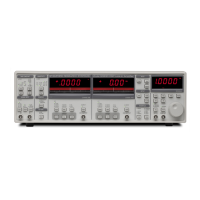
- Displays:
- Channel 1 & 2: 4 1/2 digit LED display with 40 segment LED bar graph.
- Offset: X, Y, R may be offset up to ±105% of full scale.
- Expand: X, Y, R may be expanded by 10 or 100.
- Data Buffer: 16k points from both Channel 1 and Channel 2 display.
- Inputs and Outputs:
- Channel 1 & 2 Outputs: ±10 V full scale, 10 mA max output current.
- X and Y Outputs: Rear panel, ±10 V full scale, 10 mA max output current.
- Aux Outputs: 4 BNC Digital to Analog outputs, ±10.5 V full scale, 1 mV resolution, 10 mA max output current.
- Aux Inputs: 4 BNC Analog to Digital inputs, differential, 1 MΩ input impedance, ±10.5 V full scale, 1 mV resolution.
- Trigger Input: TTL trigger input.
- Monitor Output: Analog output of signal amplifiers.
- General:
- Interfaces: IEEE-488 and RS232 standard.
- Power: 40 Watts, 100/120/220/240 VAC, 50/60 Hz.
- Dimensions: 17"W x 5.25"H x 19.5"D.
- Weight: 30 lbs.
Usage Features:
- Front Panel Control: The SR830 features a user-friendly front panel with dedicated keys for various functions and a spin knob for adjusting parameters. Parameters like internal reference frequency, phase shift, sine output amplitude, harmonic detect number, offsets, and Aux Output levels can be adjusted via the knob when displayed in the Reference display.
- Auto Functions: Includes
Auto Gain (adjusts sensitivity for optimal signal measurement), Auto Reserve (adjusts dynamic reserve to the minimum required), and Auto Phase (adjusts reference phase shift to 0°). These functions streamline setup and optimization.
- Setup Storage and Recall: The instrument can store up to 9 complete setups in non-volatile memory, allowing users to save and recall configurations easily.
- Input Configuration: Supports single-ended (A), differential (A-B) voltage, or current (I) inputs, with selectable input coupling (AC/DC) and shield grounding (Float/Ground).
- Notch Filters: Built-in notch filters for line frequency (50/60 Hz) and its second harmonic (100/120 Hz) can be engaged to remove large noise signals, reducing the required dynamic reserve.
- Data Storage: An internal data buffer can store 16,383 points from both Channel 1 and Channel 2 displays at programmable sample rates (from 62.5 mHz to 512 Hz or external trigger). Data can be stored in
1 Shot or Loop modes.
- Remote Programming: Fully controllable via IEEE-488 (GPIB) and RS232 interfaces, allowing for automated measurements and integration into larger systems. Commands are ASCII-based and can be sent in upper or lower case.
Maintenance Features:
- Self-Tests: Performs internal self-tests (DATA, BATT, PROG, DSP) upon power-on to check hardware functionality.
- Firmware Revision Display: The firmware version is shown on the Reference display at power-on.
- Serial Number Display: The 5-digit serial number is displayed on the CH1 and CH2 displays at power-on.
- Display and Keypad Tests: Dedicated test modes for verifying the functionality of front panel LEDs and keys.
- Warning Messages: Displays various warning messages (e.g.,
LOCL LOut, IGAn chG, tc chnG, hAr ovEr, tc ovEr, PhAS bAd, rcal dAtA Err, undr) to alert users to operational issues or non-obvious conditions.
- Power Entry Module: Includes a fuse holder and line voltage selector for proper configuration and protection.
- Serviceability: Designed for service by qualified personnel, with internal circuit boards (CPU and Power Supply, DSP Logic, Analog Input, Keypad, Display) that are accessible for maintenance. Safety precautions, such as disconnecting power and checking the power supply LED, are emphasized before opening the unit.