Do you have a question about the ST VL53L3CX and is the answer not in the manual?
Describes the handshake mechanism and interrupt management for sequential ranging.
Details timing aspects of ranging, including handshake delay and timing budgets.
Explains the flow of driver functions for ranging measurements and calibration.
Details API function calls for system initialization before measurement.
Initiates a ranging measurement using the VL53LX_StartMeasurement() function.
Methods to determine when a measurement result is available.
Defines the structures used to hold ranging data, including target specific results.
Configures the time allocated for a single range measurement.
Optimizes internal settings based on requested ranging distance.
Allows fine-tuning of sensor parameters for specific use cases.
Enables detection and correction of smudge effects on the coverglass.
Explains how to set a different I2C address for multiple devices.
Calibrates the number of SPADs to optimize device dynamic range.
Estimates and compensates for crosstalk due to coverglass reflection.
Measures and applies offset caused by soldering or coverglass.
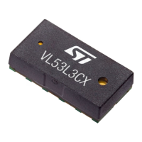
| Product Name | VL53L3CX |
|---|---|
| Measurement Range | Up to 3 meters |
| Sensing Range | Up to 3 meters |
| Operating Range | Up to 3 meters |
| Field of View (FoV) | 25 ° |
| Operating Voltage | 2.6 V to 3.5 V |
| Supply Voltage | 2.6 V to 3.5 V |
| Interface | I2C |
| Dimensions | 4.9 x 2.5 x 1.56 mm |
| Type | Time-of-Flight (ToF) sensor |
| Temperature Range | -20°C to 70 °C |
| Operating Temperature | -20°C to 70 °C |
| Laser Safety | Class 1 laser product (IEC 60825-1:2014) |