Electrical 9
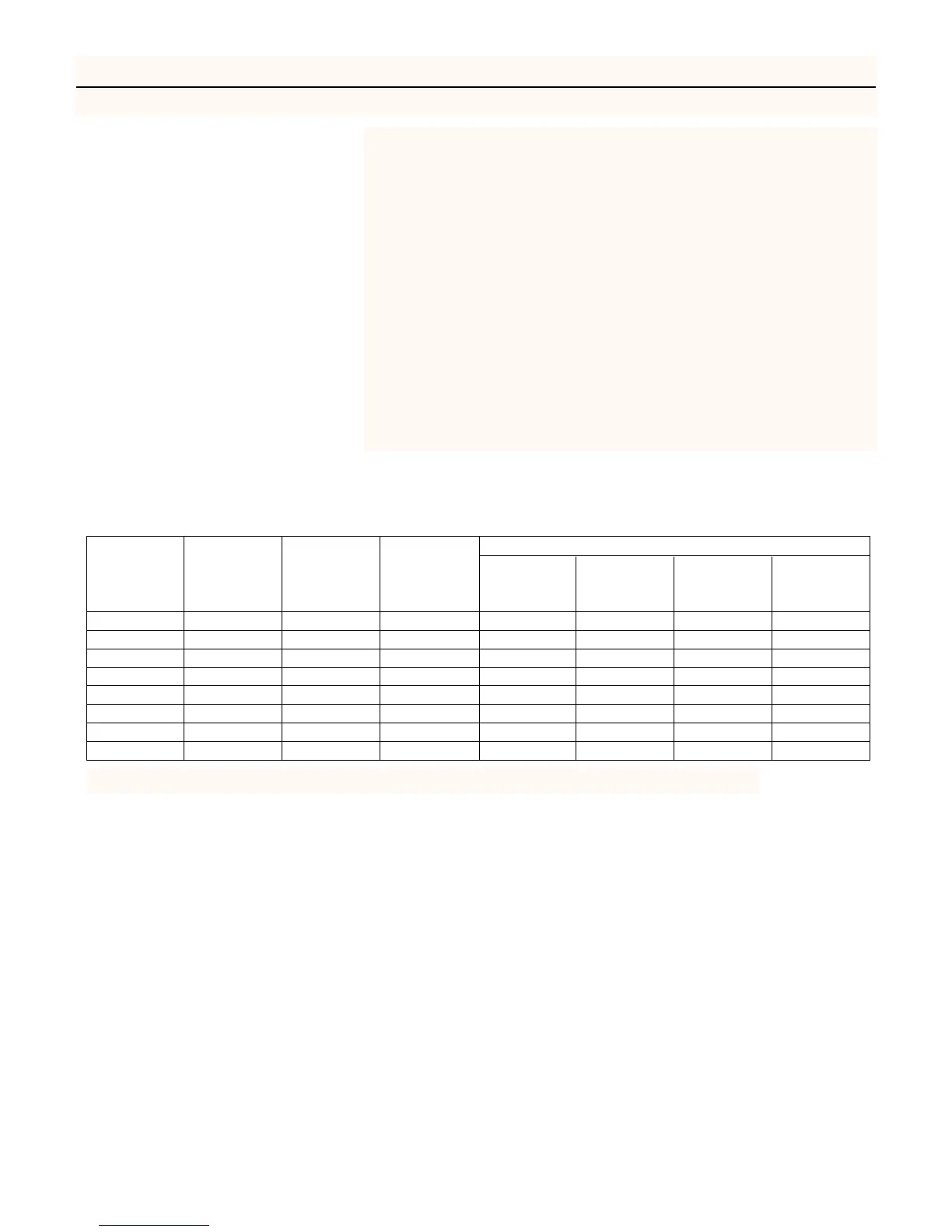
WIRING CHART – Recommended Wire and Fuse Sizes
BRANCH DISTANCE IN FEET FROM MOTOR TO METER
MAX.
FUSE*
0 51 101 201
MOTOR
VOLTS LOAD
RATING
TO TO TO TO
HP
AMPS
AMPS
50 100 200 300
1/2 115 13.0 20 12 12 10 8
1/2 230 6.5 15 14 14 14 14
3/4 115 14.8 20 12 12 8 6
3/4 230 7.4 15 14 14 14 14
1 115 19.2 25 10 10 8 6
1 230 9.6 15 14 14 14 12
1-1/2 230 12.0 15 14 14 14 12
2 230 11.5 15 14 14 14 12
(*)Time delay fuse or circuit breakers are recommended in any motor circuit.
Connection Procedure:
Step 1. Connect the ground wire first as shown in Figure 12. The ground
wire must be a solid copper wire at least as large as the power sup-
ply wires.
Step 2. There must be a solid metal connection between the pressure
switch and the motor for motor grounding protection. If the pres-
sure switch is not connected to the motor, connect the green
ground screw in the switch to the green ground screw under the
motor end cover. Use a solid copper wire at least as large as the
power supply wires.
Step 3. Connect the ground wire to a grounded lead in a service panel, to a
metal underground water pipe, to a metal well casing at least ten
feet (3M) long, or to a ground electrode provided by the power
company or the hydro authority.
Step 4. Connect the power supply wires to the pressure switch as shown in
Figure 12.