ASSEMBLY INSTRUCTIONS
11
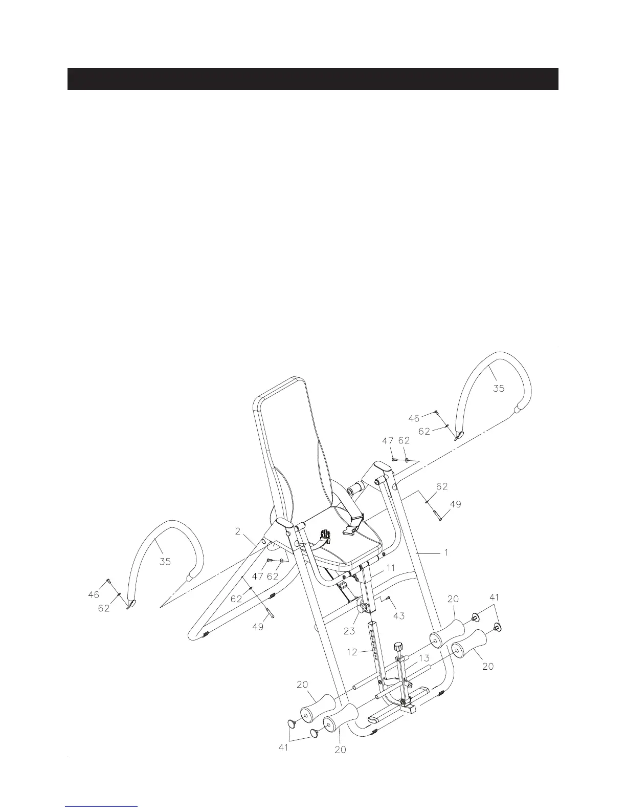
STEP 11:
Insert the upper end of the HANDRAIL(35) into the FRONT FRAME(1) and secure with
BUTTON HEAD BOLTS(M8x1.25x25mm)(47) and ARC WASHER(M8)(62). Do no tighten the
bolt. Attach the lower end of the HANDRAIL(35) to the REAR FRAME(2) with BUTTON HEAD
BOLTS(M8x1.25x15mm)(46), BUTTON HEAD BOLTS(M8x1.25x50mm)(49), and ARC WASHER(M8)
(62). Tighten the BUTTON HEAD BOLTS(M8x1.25x25mm)(47). Repeat on other side.
STEP 12:
Pull the ADJUSTMENT KNOB(23) and insert the LEG ADJUSTMENT FRAME(12) into the
SWING BAR(11). Align the holes on the LEG ADJUSTMENT FRAME(12) and the SWING BAR(11).
Then insert the ROUND HEAD BOLT(M6x1x15mm)(43) through the SWING BAR(11) and bolt into the
LEG ADJUSTMENT FRAME(12).
NOTE: The pin on the ADJUSTMENT KNOB(23) must be inserted into one of the adjustment holes in
the LEG ADJUSTMENT FRAME(12). The ADJUSTMENT KNOB(23) should be screwed in tight
to make the LEG ADJUSTMENT FRAME(12) t securely in the SWING BAR(11).
STEP 13:
Slide the FOAM PADS(20) onto both sides of the LEG ADJUSTMENT FRAME(12) and the
LEVER(13). Press the ROUND PLUGS(41) into the round tubes on the LEG ADJUSTMENT FRAME(12)
and the LEVER(13).