STHT77341 11
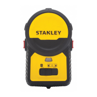
Keypad, Modes, and LED
Keypad/ Switch
Power OFF/ Pendulum Lock ON
Pendulum lock off /Self-leveling On
Pendulum lock on /Manual mode/Self-leveling
Off
• Move to the locked or unlocked position to turn the
laser tool ON.
• To turn the laser tool OFF, move to the centre
position .
•
• Side Vertical Beam ON / OFF
Press to turn the side vertical beam ON./OFF
Modes
Laser Beam Available Modes
• Cross Line ON (D
1
): Horizontal Beam Line and
Vertical Beam Line ON
• All beams ON (D
2
): Horizontal Beam Line,
Vertical Beam Line and Side Beam Line ON
• All beams OFF
Self-Leveling (See figures
C
and
D
)
• The pendulum lock on the laser tool needs to be
switched to the unlocked position to enable self-leveling.
Manual Mode (See figures
C
and
D
)
• The laser tool can be used with the pendulum lock in the
locked position when it is required to position the laser
tool at various angles to project non-level straight lines.
LED /Out-of-Level Indicator Operation (See figure
A
# 5 )
LED OFF
Power is OFF/ Pendulum Lock is ON
Power is ON, pendulum lock is OFF and laser
unit is within self-leveling range.
Solid RED
• Power is ON, pendulum lock is OFF, and
laser unit is out of level.
• or
• Power is ON , pendulum lock is ON/ Self-
Leveling is OFF.
QuickLink ™ Bracket Overview
Figure F -QuickLink ™ Bracket
10. T-nut to mate with slots on Laser Unit.
11. Jaw Tightening Knob.
12. Bracket Tightening Knob .
13. Hang holes for screw mounting. (34mm apart)
14. 1/4-20” threaded mount.
15. Adjustable Jaw
Bracket Applications
• The QuickLink bracket can be mounted in various
positions by clamping the jaws to round or flat objects
such as a tripod pole, door or bench and tightening the
knobs. ( See figure
F
: #11 & #12)
• The QuickLink bracket can be mounted on a vertical
surface using the hang holes provided. (See figure
F
#13)
•
• The QuickLink bracket can be attached to the bottom
of the laser unit using the 1/4-20” threaded mount
(Figure
F
#14 and figure
A
#1) or the t-nut and
slot connection.

 Loading...
