5
ENGLISH
(Original instructions)
Warning! The vibration emission value during actual use of
the power tool can differ from the declared value depending
on the ways in which the tool is used. The vibration level may
increase above the level stated.
When assessing vibration exposure to determine safety
measures required by 2002/44/EC to protect persons regularly
using power tools in employment, an estimation of vibration
exposure should consider, the actual conditions of use and the
way the tool is used, including taking account of all parts of the
operating cycle such as the times when the tool is switched off
and when it is running idle in addition to the trigger time.
Labels on tool
The following symbols are shown on the tool:
:
Warning! To reduce the risk of injury, the user
must read the instruction manual.
Electrical safety
#
This tool is double insulated; therefore no earth
wire is required. Always check that the power
supply corresponds to the voltage on the rating
plate.
u If the supply cord is damaged, it must be replaced by the
manufacturer or an authorised Stanley FaxMax Service
Centre in order to avoid a hazard.
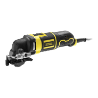
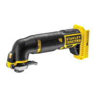
Features
This tool includes some or all of the following features.
1. Trigger switch
2. Lock-on button
3. Saw blade locking lever
4. Blade clamp
5. Shoe plate
6. Shoe beveling lever
7. Variable speed control
8. Cutting action lever
9. Shoe sleve
10. LED work light
Assembly
Warning! Before assembly, remove the battery from the tool
and make sure that the saw blade has stopped. Used saw
blades may be hot.
Fitting and removing the saw blade (g. A)
u Hold the saw blade (11) with the teeth facing forward.
u Lift the saw blade locking lever (3) upwards.
u Insert the shank of the blade fully into the blade clamp (4)
as far as it will go.
u Release the lever.
u To remove the saw blade (11), lift the saw blade locking
lever (3) upwards and pull the blade out.
Fitting and removing the shoe sleeve (g. B)
The non scratch shoe sleeve (9) should be used when cutting
surfaces that scratch easily, such as laminate, veneer, or
paint. It can also be used to protect the shoe surface during
transportation and storage.
To attach shoe sleeve:
u place the front of the shoe plate (5) into the front of the
shoe sleeve (9).
u Lower the tool into the shoe sleve (9). The shoe sleeve
will click securely onto the rear of the shoe.
To remove shoe sleeve:
u Grasp the shoe sleeve from the bottom at the two rear
tabs and pull down and away from the shoe plate (5).
Use
Warning! Let the tool work at its own pace. Do not overload.
Warning! Never use the tool when the saw shoe is loose or
removed.
Switching on and off (g. C)
Warning! Check that the tool is not locked ON before con-
necting it to a power supply. If the trigger switch is locked ON
when the tool is connected to the power supply, it will start im-
mediately. Damage to your tool or personal injury may result..
u To switch the tool on, press the trigger switch (1). The tool
speed depends on how far you press the switch.
u For continuous operation, press the lock-on button (2) and
release the variable speed switch. This option is available
only at full speed.
u To switch the tool off, release the trigger switch. To switch
the tool off when in continuous operation, press the trigger
switch once more and release it.
Variable speed control
The variable speed on/off switch offers a choice of speeds for
greatly improved cutting rates in various materials.
u To set the speed, turn the variable speed control (7) to the
required setting.
Bevel cutting (g. D & E)
The shoe plate can be set to a left or right bevel angle of up
to 45°.

 Loading...