Inside
corner
Mitre angle
Left at
45 º
Right at
45 º
0 º 0 º
Moulding
position
Bottom
against
table
Bottom
against
table
Top
against
nce
Bottom
against
fence
Finished
side
Keep left
side of
cut
Keep
right side
of cut
Keep left
side of
cut
Keep left
side of
cut
Outside
corner
Mitre angle
Left at
45 º
Right at
45 º
0 º 0 º
Moulding
position
Bottom
against
table
Bottom
against
table
Top
against
nce
Bottom
against
fence
Finished
side
Keep left
side of
cut
Keep
right side
of cut
Keep
right side
of cut
Keep
right side
of cut
Crown moulding cut (g. L)
Crown moulding can only be cut at on the table with this
mitre saw.
● This mitre saw has special mitre stops on 31.6° left and
right and a bevel stop of 33.9° for special crown moulding,
i.e. 52° between the back of the moulding and the top
at surface that ts against the ceiling; 38° between the
back of the moulding and the bottom at surface that ts
against the wall.
● Refer to the following table to make this crown
moulding cut:
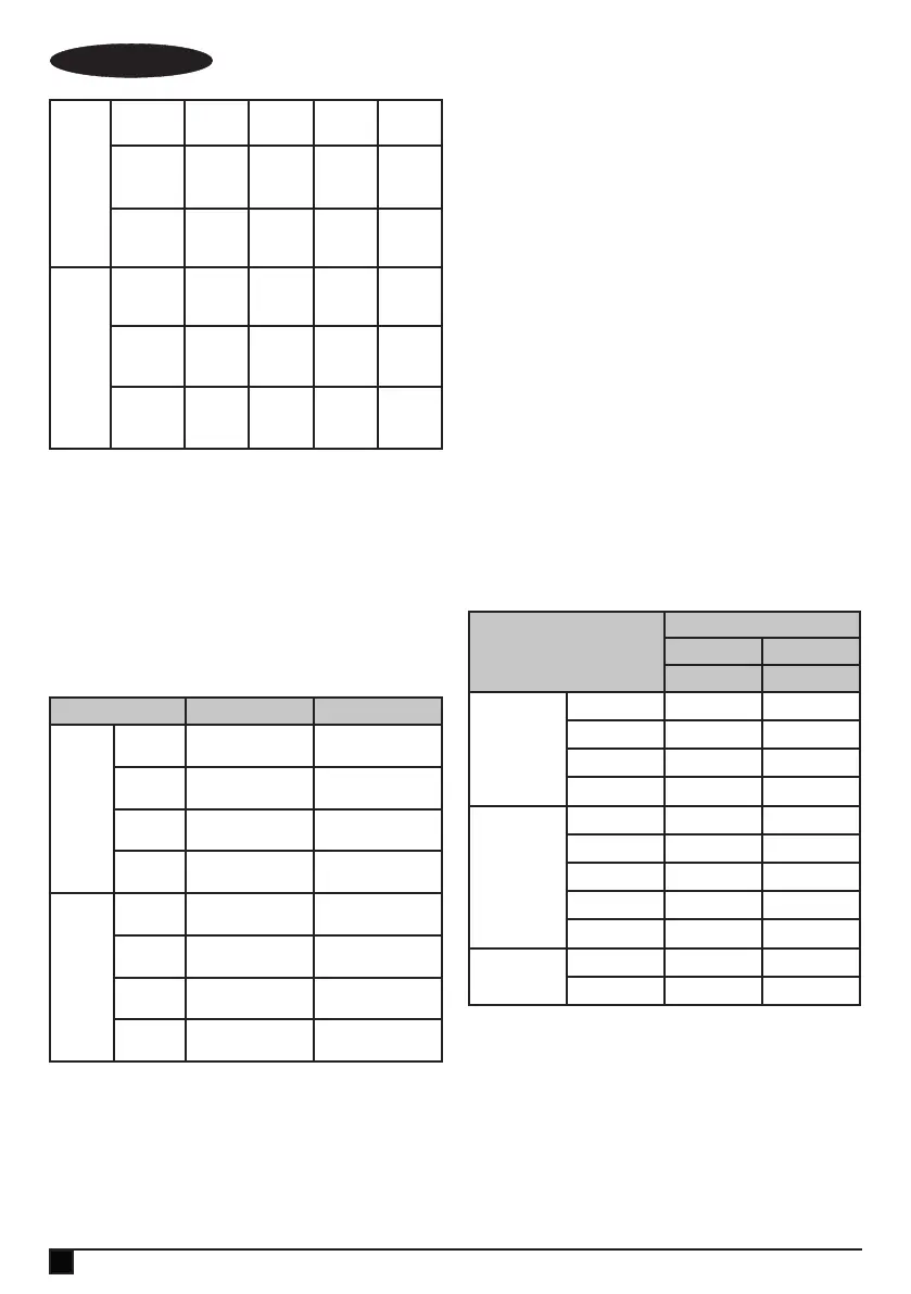
Settings Left side Right side
Inside
corner
Mitre
angle
Right 31.6 º Left 31.6 º
Bevel
angle
33.9 º 33.9 º
Moulding
position
Top against fence Bottom against fence
Finished
side
Keep left side of cut Keep left side of cut
Outside
corner
Mitre
angle
Right 31.6 º Left 31.6 º
Bevel
angle
33.9 º 33.9 º
Moulding
position
Bottom against fence Top against fence
Finished
side
Keep right side of cut Keep right side of cut
Note: These special stops can not be used with 45°
crown moulding.
Note: Since most rooms do not have angles of exactly 90°,
ne tuning is needed, always make a test cut to conrm the
correct angles.
Setting the cutting depth (g. M)
The depth of cut can be preset for even and repetitive
shallow cuts.
● Adjust the cutting head down until the teeth of the blade
are at the required depth of cut.
● While holding the upper arm in position, turn the
stop knob (47) until it touches the stop plate (49).
● Check the blade depth by moving the cutting head front
to back through the full motion of a typical cut along the
control arm.
Carrying the tool (g. B, J, H, N)
● Loosen the mitre detent lever (11) (g. B) and turn the
table all the way to the right. Lock the table at the 45°
mitre angle.
● Pull the cutting head to the front of the saw and lock the
carriage with the lock knob (48) (g. J).
● Lower the cutting head and push in the lock pin (46)
(g. H).
● Carry the mitre saw with the front and the rear carrying
handles (24, 27).
@
Warning! Do not carry the machine by the guard.
Blade and tooth type
Material
Tooth type
600 ~ 100T 24 ~ 100T
TCG ATB
Wood
Lumber ● ●
Plywood ● ●
Hardwood ● ●
Chipboard ● ●
Plastic
PVC ●
ABS ●
Acrylic ●
PC ●
PS ●
Non-ferrous
metal
Aluminium ●
Copper ●
Your mitre saw has been supplied with a negative rake saw
blade. It is advisable to use a negative rake saw blade.
● TCG type - For cutting aluminium sheets, tubing
extrusions and other non-ferrous metals such as
copper, brass.
● ATB type - For general cutting and trimming of wood,
plywood, and sizing pressboard, hardboard, and particle
board, when a neat cut is needed.
Always use a negative rake blade when cutting non-
ferrous metals.
14
ENGLISH
(Original instructions)

 Loading...