12- ENG
F. Detergent Tank: Feeds cleaning agents into the pump to mix with the water. See
How
To Apply Chemicals/Cleaning Solvents
instructions in
Operation
section.
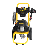
G. Handle
H. Frame
I. Pump Outlet
J. Pump Inlet
K. Quick Connect Nozzles
L. Adjustable Pressure Regulator: Use the adjustable pressure regulator
to increase and decrease the pressure. Refer to the Adjustable Pressure
Regulator Adjustmentparagraph.
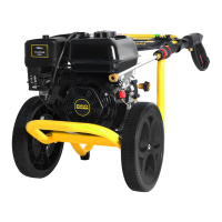
BASIC ELEMENTS OF AN ENGINE
Refer to the Engine Owner’s Manual for location and operation of enginecontrols.
Choke Control: Opens and closes carburetor chokevalve.
Starter Grip: Pulling starter grip operates recoil starter to crankengine.
Engine Switch: Enables and disables ignitionsystem.
ASSEMBLY INSTRUCTIONS (FIG. 2 – 4)
1. Locate and remove all loose parts from thecarton.
2. Cut four corners of the carton from top to bottom and lay the panelsflat.
3.
Place handle (G) onto frame (H),
G
H
2
Q
2A
K
depress the snap buttons, and slide
the handle assembly onto the frame
until snap buttons snap intoplace.
NOTICE: Risk of personal injury. Avoid
placing hands between handle and frame
when assembling to preventpinching.
4. Remove the colored quick-connect
nozzles (K) from the plastic bag and insert them into correct grommet on the nozzle
holder. Nozzles are color coded to match colored nozzles on label (Q).
5. Slide the axle pin through the wheel and one of the flat washers (Figure 3). Slide
the axle pin through the hole in the frame and other flat washer (Figure 3A). Slide
clip through hole in axle pin to secure wheel in place (Figure 3B). Repeat same steps
for second wheel.
NOTICE: Keep machine level during wheel installation process. Do
not tilt, tip over, or turn upside down to install wheel kit. May
causedamage!
3
3A
3B
 Loading...