7
ENGLISH
LABELS ON TOOL
In addition to the pictographs used in this manual, the
labels on the tool show the following pictographs:
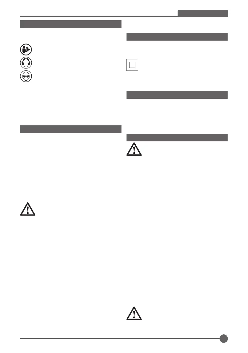
Read instruction manual before use.
Wear safety glasses.
Wear ear protection.
Date Code Position (Fig. B)
The Date Code (13), which also includes the year of
manufacture, is printed into the housing.
Example:
2017 XX XX
Year of Manufacture Package Contents
THE PACKAGE CONTAINS
1 Jig saw
1 Blade
1 Instruction manual
1 Wrench
1 Warranty card
1 Service center list
♦ Check for damage to the tool, parts or accessories
which may have occurred during transport.
♦ Take the time to thoroughly read and understand this
manual prior to operation.
Description (Fig. A to J)
WARNING: Never modify the power tool or any
part of it. Damage or personal injury could result.
1.Trigger switch
2.Lock-on button
3.Speed controller
4.Dust cover
5.Blade clamp actuator
6.Blade clamp
7.Saw blade
8.Pendulum Stroke selector
9.Shoe plate
10.Dust extraction outlet
11.Wrench
12.Screw-blade clamp
13.date code
14.Vacuum nozzle (optional)
15.Screw-shoe plate
16.Cutting line
17.Rip fence (optional)
18.Screw (optional)
19.Clamp bar (optional)
ELECTRICAL SAFETY
Only one voltage is applicable to this tool. Be sure to check
that the power supply corresponds to the voltage on the
rating plate.
Your Stanley tool is equipped with double
insulation, hence, it does not require to be
earthed
When the power cord is damaged, have it sent to a
STANLEY service center for replacement to specially
prepared cables.
USING AN EXTENSION CABLE
If an extension cable is required, use an approved 3–core
extension cable suitable for the power input of this tool
(see Technical Data).The minimum conductor size is 1.5
mm2; the maximum length is 30 m.
When using a cable reel, always unwind the cable
completely.
ASSEMBLY AND ADJUSTMENT
WARNING: To reduce the risk of serious
personal injury, turn tool off and disconnect tool
from power source before making any
adjustments or removing/installing attachments or
accessories. Before reconnecting the tool, depress and
release the trigger switch to ensure that the tool is off. An
accidental start-up can cause injury.
Fitting the saw blade:
(SJ60) (Fig.A-1)
♦ Lift dust cover (4).
♦ Hold the saw blade (7) as shown, with the teeth facing
forward.
♦ Push the blade clamp actuator (5) away from the shoe
plate (9).
♦ Insert the shank of the saw blade into the blade clamp
(6) as far as it will go.
♦ Release the blade clamp actuator (5).
♦ Turn down dust cover (4).
(SJ45) (Fig. A-1)
♦ Loosen (do not remove) the two screws-blade clamp.
(12).
♦ Hold the saw blade (7) with the teeth facing forward.
♦ Insert the shank of the saw blade (7) into the blade
clamp (6) as far as it will go.
♦ Slightly tighten the two screws-blade clamp (12)
alternately to position the blade, then fully tighten the
two screws-blade clamp (12).
WARNING: 1.Always clean out all chips or
foreign matter adhering to blade and/or blade
holder. Failure to do so may cause insufficient
tightening of the blade, resulting in a serious personal
injury.

 Loading...