• The maximunm speed of the saw blade shall always be
greater than or at least equal to the speed marked on the
rating plate of the tool.
• The saw blade diameter must be in accordance with the
markings on rating plate of the tool.
• Consider applying specially designed noisereduction
blades.
• Do not use high steel (HS) saw blades.
• Do not use cracked or damaged saw blades.
• Ensure that the chosen saw blade is suitable for the
material to be cut.
• Always wear gloves for handling saw blades and rough
material. Saw blades should be carried in a holder
wherever practicable.
Power connections
Before connecting the machine to the power line, make sure
the switch (8) is in the “OFF” position and be sure that the
electric current is of the same characteristics as indicated on
the machine. All line connections should make good contact.
Running on low voltage will damage the machine.
DANGER! Do not expose the machine to rain or
operate the machine in damp locations.
Before connecting the machine to the power source, make
sure the switch is in the “OFF” position.
SAFETY OF OTHERS
• This appliance is not intended for use by persons
(including children) with reduced physical, sensory or
mental capabilities, or lack of experience and knowledge,
unless they have been given supervision or instruction
concerning use of the appliance by a person responsible
for their safety.
• Children should be supervised to ensure that they do not
play with the appliance.
RESIDUAL RISKS
Additional residual risks may arise when using the tool which
may not be included in the enclosed safety warnings. These
risks can arise from misuse, prolonged use etc. In spite of the
application of the relevant safety regulations and the
implementation of safety devices, certain risks cannot be
avoided. These are:
• Injuries caused when changing any parts, blades or
accessories.
• Injuries caused by prolonged use of a tool. When using
any tool for prolonged periods ensure you take regular
breaks.
• Impairment of hearing.
• Health hazards caused by breathing dust developed when
using your tool (example: working with wood, especially
oak, beech and MDF.)
ELECTRICAL SAFETY
Your tool needs to be earthed. Always check that the main
voltage corresponds to the voltage on the rating plate.
WARNING
! If the power cord is damaged, it must
be replaced by the manufacturer, authorized
STANLEY Service Center or an equally qualified
person in order to avoid damage or injury. If the
power cord is replaced by an equally qualified
person, but not authorized by STANLEY, the
warranty will not be valid.
USING AN EXTENSION CABLE
If it is necessary to use an extension cable, please use an
approved extension cable that fits the tool’s power input
specifications. The minimum cross-sectional area of the
conducting wire is 1.5 sq. mm. Cables should be untangled
before reeling up.
Cable cross-sectional
area (mm
2
)
Cable rated current
(Ampere)
0.75 6
1.00 10
1.50 15
2.50 20
4.00 25
Voltage Amperes Cable rated current (Ampere)
110-127 0 - 2.0 6 6 6 6 6 10
2.1 - 3.4 6 6 6 6 15 15
3.5 - 5.0 6 6 10 15 20 20
5.1 - 7.0 10 10 15 20 20 25
7.1 - 12.0 15 15 20 25 25 -
12.1 - 20.0 20 20 25 - - -
220-240 0 - 2.0 6 6 6 6 6 6
2.1 - 3.4 6 6 6 6 6 6
3.5 - 5.0 6 6 6 6 10 15
5.1 - 7.0 10 10 10 10 15 15
7.1 - 12.0 15 15 15 15 20 20
12.1 - 20.0 20 20 20 20 25 -
Cable length (m)
7.5 15 25 30 45 60
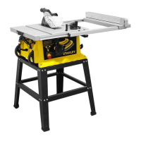
8. On/Off switch
9. Leg stand
10. Bevel adjustment locking knob
12. Leg stand locking bolt
13. Blade tilting wheel
14. Locking handle for extension table
15. Locking handle for rip fence
16. Extension table
17. Spanner wrench
18. Guide rail
19. Push stick
20. Table insert
21. Groove (a)
21. Groove (b)
22. Overloaded protector
assembled.
1. Identify the parts and fittings
is printed into the housing.
may have occurred during transport.
manual prior to operation.
This tool includes some or all of the following features.
1. Saw table
2. Blade guard
3. Riving knife
4. Saw blade
5. Rip fence
6. Mitre guage
7. Transportation wheels
must read the instruction manual before use.
Wear ear protection.
Wear safety glasses or goggles.
/min.
 Loading...