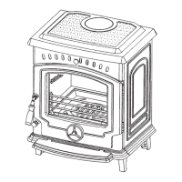
Fig.1
OPERATION
The controls are located on the lower right hand
side of the stove. See Fig. 1.
A switch is in the ‘ON’ position when the red indi-
cator mark of the switch is visible.
Connect the fire to your electricity supply.
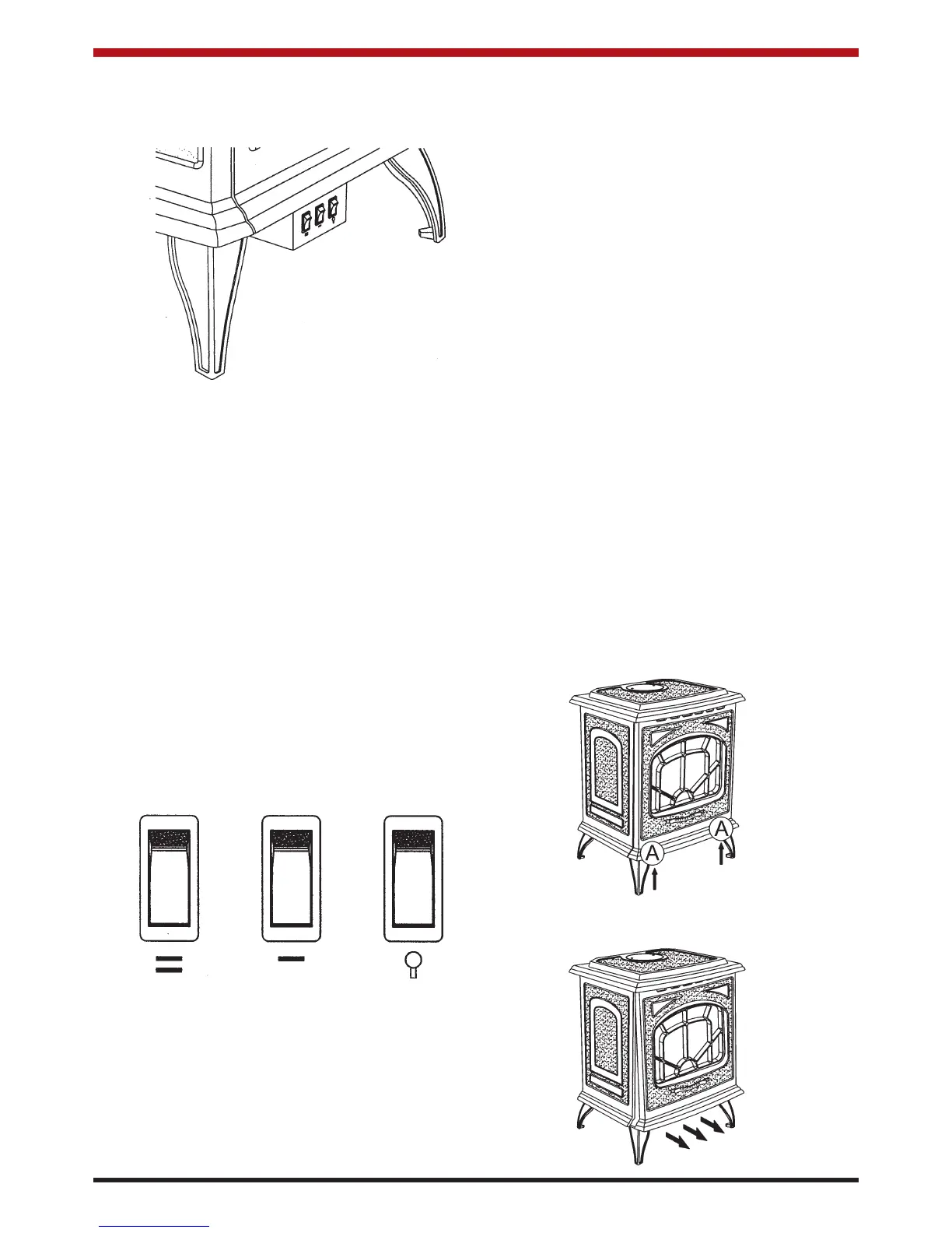
FLAME EFFECT
Press the third switch to the “on” position. The
flame effect will now operate.
HEATING UNIT
You have a choice of (0.6 kW) output or (1.2 kW)
output by simply switching the controls as follows:
LOW HEAT SETTING: Press the second switch
marked - to the “on” position.
HIGH HEAT SETTING: Press the first switch
marked = to the “on” position. The second switch
marked - must also be “on”.
*In order to operate the heating the flame effect
switch must be operating.
(See Fig.2)
Fig.2
the heater if; for any reason; it overheats. Should
the cut-out operate, determine the reason for the
overheating before resetting the cut-out. To reset
the cut-out, switch off or unplug the heater for a
few minutes, after which normal operation may be
resumed.
MAINTENANCE
WARNING: ALWAYS DISCONNECT FROM THE
POWER SUPPLY BEFORE ATTEMPTING ANY
MAINTENANCE.
LAMP REPLACEMENT
To gain access to the lamps, carefully remove the
firebox door. See Fig. 3.
Allow at least 10 minutes for light bulbs to cool off
before touching bulbs to avoid accidental burning
of skin.
To remove firebox door:
1. Hold the cast iron front panel at the bottom
and lift upwards and out from the stove.
Once free of the locating tabs, the panel
can be dropped down; freeing it from the
top of the stove.
2. Place the cast iron front panel on a non-
abrasive surface, away from any traffic to
ensure that it does not get damaged.
THERMAL SAFETY CUT-OUT
A thermal safety cut-out is incorporated in the
heater to prevent damage due to overheating.
This can happen if the heat outlet was restricted in
any way.
The manual reset thermal cut-out will switch off
5
Fig.3
 Loading...