This document is an owner's manual and safety instructions for a STARK Power Trowel with a Hook Disc Pan. The manual covers two models: ITEM #61041 (equipped with a Loncin 200F engine) and ITEM #61042 (equipped with a GX160 engine).
Function Description:
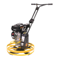
The STARK Power Trowel is a piece of industrial equipment designed for finishing concrete surfaces. It uses a rotating hook disc pan to achieve a smooth and level finish on concrete. The machine is powered by an internal combustion engine, either a Loncin 200F or a GX160, depending on the model. The operation involves controlling the trowel's movement and blade angle to achieve the desired concrete finish.
Important Technical Specifications (Derived from Parts Information and Assembly):
While specific power output or disc diameter are not explicitly stated, the manual provides details on various components that give insight into its construction and operation:
- Engine Types: Loncin 200F (for #61041) and GX160 (for #61042). These are common small gasoline engines, indicating the trowel is gasoline-powered.
- Fasteners: A variety of bolts, nuts, and gaskets are used, including:
- Flat gasket: 6182 (4pcs), 08 (2pcs)
- Hexagon screw: M6*12 (4pcs)
- Countersunk head hexagon screw: 5/16-24-16 (2pcs)
- Double end bolt: M8*40 (4pcs)
- Flange nut: M8 (4pcs)
- Shaft head bolt: 5/16-24-25 (1pc)
- Spring gasket: 08 (1pc)
- Tapered flat gasket: 8*30 (1pc)
- Outer hexagon bolt: M8*35 (1pc)
- Locknut: M8 (1pc)
- Key Components:
- Flat key: 4.78*50 (1pc) - essential for securing rotating components to the engine shaft.
- Clutch adjusting pad: Ø20 (4pcs) - suggests a clutch mechanism for engaging/disengaging power to the trowel.
- Belt cover bracket (1pc)
- Clutch assembly: Ø19.05 (1pc) - confirms the presence of a clutch system.
- Ribbon (4pcs)
- V belt: A-584 (1pc) - indicates a belt-driven power transmission system from the engine to the trowel mechanism.
- Lower handle (1pc) - includes lifting screw, upper handle retaining bolt M8*120 (1pc), and bakelite bolt.
- Upper handle (1set)
- Belt cover (1set)
- Main body (1set)
- Engine (1pc) - includes throttle lever assembly.
- Assembly Process: The assembly images and instructions detail how the engine, clutch, belt, handles, and various covers are connected to the main body, highlighting the modular nature of the design. The process involves securing the lower and upper handles, mounting the engine onto a support plate, installing the clutch and belt, and attaching covers.
Usage Features:
- Engine Control Module: The manual emphasizes testing the engine control module's function before operation, indicating its importance for safe and proper use.
- Throttle Lever Assembly: The engine includes a throttle lever assembly, which is fixed to the handle, allowing the operator to control engine speed and thus the trowel's rotation.
- Handle-Based Operation: The presence of upper and lower handles suggests a walk-behind design, where the operator guides the trowel across the concrete surface.
- Safety Devices: The machine is equipped with safety devices and guards (e.g., belt guard) that must be in place and working correctly during operation.
- Application: Specifically designed for concrete finishing, not for other industrial tasks.
- Work Area Requirements: Requires a clean, dry, well-lit, and clutter-free work area.
- Environmental Considerations: Not to be run indoors or in enclosed areas without adequate ventilation due to poisonous carbon monoxide gas from engine exhaust.
- Pop-ups in Concrete: Operators are warned not to use the trowel around concrete pop-ups that are lower than the lowest ring on the ring guard, indicating a minimum clearance requirement.
Maintenance Features:
- Regular Inspection: Operators are instructed to inspect the work area and the machine itself before each use, checking for damaged or worn parts.
- Part Replacement: Damaged or worn parts must be replaced immediately.
- Periodic Maintenance: The manual states that periodic maintenance and occasional repairs are necessary for safe and proper operation over time.
- Cleaning: The machine should be kept clean, and labels legible.
- Spark Plug Disconnection: For gasoline engines, the spark plug must be disconnected before servicing to prevent accidental start-up.
- Blade Handling: Blades must be handled carefully as they can develop sharp edges.
- Fuel Valve: The fuel valve on engines should always be closed when the machine is not in use.
- No Cleaning While Running: Never attempt to clean or service the machine while it is running due to the risk of severe injury from rotating parts.
- No Fuel for Cleaning: Gasoline or other flammable solvents should not be used to clean parts, especially in enclosed areas, due to explosive fumes.
- Engine Maintenance: Warnings against cranking a flooded engine with the spark plug removed and testing for spark if the engine is flooded or gasoline fumes are present.