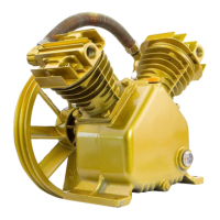
This document is an owner's manual and safety instructions for a Stark 5HP Twin Cylinder Compressor Pump, Item: 65027.
The compressor pump is designed as a replacement for a similarly rated pump on an existing compressor system. It is not intended for constructing a new compressor from scratch, as this would require a qualified engineer to ensure all safety and control elements are properly integrated. The pump itself is a twin-cylinder design, featuring a large pump pulley, two air filter assemblies, two cylinders, and two cylinder heads. Key components visible include an oil fill plug, oil sight glass, oil drain plug, and crankcase.
The manual emphasizes general safety warnings, precautions, and instructions to prevent electric shock, fire, and serious injury. It stresses the importance of reading and understanding all assembly and operation instructions. Key safety points include:
- Work Area: Keep the work area clean, well-lit, and free from explosive atmospheres.
- Bystanders: Keep children and bystanders away from an operating compressor pump.
- Operator Alertness: Stay alert and use common sense; do not operate while tired or under the influence of drugs, alcohol, or medication.
- Personal Protective Equipment: Always wear ANSI-approved eye protection.
- Maintenance: Disconnect the compressor motor from the power source before any adjustments, accessory changes, or storage. Maintain the pump by keeping it clean, dry, and free from oil and grease. Check for misalignment, binding, or damaged parts.
- Storage: Store idle pumps out of reach of children and untrained users.
- Intended Use: Use the pump only for its intended operations; misuse can lead to hazardous situations.
- Servicing: Have the compressor pump serviced by a qualified repair person using identical replacement parts.
- Pulleys and Belts: Use a safety guard (not included) to cover the Air Compressor Pump Pulley (58), V-belts (not included), and motor pulley (not included) before operation.
- Oil Level: Verify sufficient oil before every use. Operating with low or no oil causes permanent damage and voids the warranty.
- Accessories: Only use accessories or attachments recommended by the manufacturer to avoid injury.
- Alignment: Ensure proper alignment between the motor and pump to prevent damage. Use a straight edge to check alignment.
- Motor and Pulley Size: The pump requires a 5 HP electric motor and pulley (both not included) capable of turning the pump pulley at approximately 1050 rpm.
- Installation: Install the motor, pulley belts, and pulley belt cover securely.
- Equipment Rating: Ensure all connected equipment is rated to the appropriate capacity and can handle the maximum pressure of the pump.
- Burns: Avoid touching hot components like cylinders, cylinder heads, and air outlet components during operation.
- OSHA Guidelines: Industrial applications must follow OSHA guidelines.
- Labels: Maintain legible labels and nameplates.
- Children: This product is not a toy; keep it out of reach of children.
- Chemical Warning: Brass components contain lead, a chemical known to cause cancer and birth defects in California.
- Fire/Explosion Risk: Do not spray flammable liquid in confined areas or towards hot surfaces. Ensure good ventilation. Do not smoke or operate near sparks/flames. Keep the compressor at least 20 feet away from explosive vapors.
- Bursting Risk: Do not adjust the regulator higher than the marked maximum pressure of the attachment.
- Injury Risk: Do not direct the air stream at people or animals.
- Breathing Air: Do not use to supply breathing air.
- Unattended Operation: Do not leave the compressor unattended while plugged in. Unplug after use.
- Ventilation: Keep the compressor well-ventilated; do not cover it during use.
- Tank Maintenance: Drain the tank daily and after use to prevent internal rust, tank failure, and explosion.
- Valve Cover: Do not remove the valve cover or adjust internal components.
- Pressure Release: Release pressure in the storage tank before moving the unit.
- Air Line Components: All air line components (hoses, pipe, connectors, filters, etc.) must be rated for a minimum working pressure of 150 PSI or 150% of the maximum system pressure, whichever is greater.
- Extension Cords: Use of an extension cord is not recommended. If used, refer to Table A for recommended minimum wire gauge based on amperage and length (120 Volt). Ensure the cord is in good condition and heavy enough to carry the current.
- Level Surface: Operate the unit on a level surface.
- Pacemakers: Individuals with pacemakers should consult their physician before use due to potential electromagnetic interference.
Assembly:
The assembly process focuses on installing the pump pulley onto the crankshaft:
- Apply grease to the crankshaft slot and insert the Woodruff Key (50).
- Ensure the pump pulley's center hole and keyway are clean.
- Apply grease to the pulley's hole and keyway. Align the keyway with the Woodruff Key and slide the Pump Pulley (58) over the Crankshaft (49), with the indented side facing out.
- Slide the Pulley Washer (59) and Spring Washer (60) onto the Bolt (61). Insert the bolt through the pump pulley and thread it counterclockwise into the crankshaft. Tighten with a wrench.
- Warning: Do not force or hammer the pump pulley.
- Note: The bolt has a left-hand thread; turn counterclockwise to tighten.
Installation:
The installation section details how to integrate the compressor pump into an existing system:
- Positioning: Place the pump on a flat, level, and strong mounting surface, ensuring easy access to the Oil Drain Plug (36).
- Motor and Pulley Calculation: Use a motor with the appropriate size pulley to achieve the required pump RPM. The manual provides a formula: (Pump Pulley Diameter x Pump Working RPM) / Motor RPM = Motor Pulley Diameter. For example, a 14.5" pump pulley and 1050 pump RPM with a 1725 RPM motor requires an 8.8" motor pulley.
- Alignment: Ensure the Pump Pulley (58) is perfectly aligned with the motor pulley (not included) using a straight edge.
- Note: The pump pulley should be installed for counterclockwise rotation when facing the pulley side of the pump.
- Clearance: Verify the pump pulley turns freely without overhanging the mounting surface.
- Belt Installation: Place two V-groove belts (not included) over the pump pulley and motor pulley.
- Tensioning: Pull the compressor pump until properly aligned and the belts are tight. Recheck alignment.
- Mounting Holes: Use the pump base as a template to mark and drill four 3/8" diameter holes in the mounting surface.
- Securing: Secure the pump to the mounting surface with 3/8" diameter grade 5 or better bolts, washers, lock washers, and nuts (all not included).
- Belt Tension Adjustment: Adjust belt tension with the motor. There should be 1/2" deflection or less at mid-span when pressing down on the belts. Tighten all mounting hardware.
- Plumbing: Connect plumbing hardware (not included) from the 1”-16 UN Air Outlet to the air destination (e.g., air pressure tank, not included), routing tubing in the shortest path.
- Additional Components: Depending on the air tool, additional components like an in-line oiler, filter, or dryer (sold separately) may be needed.
- Safety Guard: Install a safety guard (not included) covering all sides of the moving belts and pulleys, with about one inch of clearance from moving parts.
- Warning: Do not operate without a safety guard.
- Oil Fill: Fill the crankcase with Air Compressor Oil (sold separately) before operation.
Checking the Oil:
- Check the oil level before each operation.
- Fill the pump crankcase with SAE 30W, non-detergent Air Compressor Oil (sold separately).
- Important: Running with no oil or low oil will damage equipment and void the warranty.
- The oil level should be at the center of the "FULL" level on the oil sight glass. Add oil as needed, ensuring it does not go below "LOW" or above "OVERFILL".
- To Add Oil: Remove the Oil Fill Plug, pour oil using a funnel until it reaches the "FULL" level, then replace the plug.
- Note: SAE 30W, non-detergent oil is recommended.
- Change the compressor oil after the first hour of use to remove debris.
- Caution: Do not add or change oil while the compressor is in operation; allow it to cool.
- Note: The pump consumes oil during operation, so check the level before every use.
Maintenance Schedule:
The manual provides a maintenance schedule:
- Daily: Check oil level, check for oil leaks, check all nuts and bolts are tight, check for abnormal noise or vibration, check for air leaks.
- Weekly: Inspect belts, inspect air filters.
- Monthly: Inspect oil breather plug, check belt adjustment.
- Every 6 Months: Replace pump oil.
Oil Maintenance:
- Check oil periodically for clarity. Replace oil if it appears milky, contains debris, or every 6 months/100 hours of runtime, whichever comes first. More frequent changes are needed in harsh environments (high heat, high humidity).
- Caution: Allow the pump to cool before changing oil.
- Procedure:
- Place a container under the Oil Drain Plug.
- Remove the Oil Fill Plug to allow airflow.
- Remove the Oil Drain Plug to drain oil.
- Replace the Oil Drain Plug once drained.
- Fill with new SAE 30W, non-detergent Air Compressor Oil to the FULL level on the Oil Sight Glass.
- Replace and tighten the Oil Fill Plug.
- Discard old oil according to regulations.
Air Filter Maintenance:
- Check air filters weekly for replacement. More frequent replacement is needed in dirty environments.
- Procedure:
- Remove Air Filter Front Covers.
- Remove Air Filter Elements.
- Replace with new Air Filter Elements.
- Replace Covers.
Troubleshooting:
The manual includes a troubleshooting guide for common issues:
- Compressor builds pressure too slowly: Possible causes include overfilled/thick crankcase oil, cold working environment, or loose fittings. Solutions involve draining/refilling oil, moving to a warmer location, or checking/tightening fittings.
- Compressor not building enough air pressure: Possible causes include dirty/clogged air filters, undersized compressor, loose fittings, narrow hoses, thick crankcase oil, or high altitude. Solutions include cleaning/replacing filters, using a larger compressor, checking/tightening fittings, using wider hoses, draining/refilling oil.
- Overheating: Possible causes include dirty/clogged air filters, thin/incorrect crankcase oil, low crankcase oil level, dusty environment, or unit not on a level surface. Solutions include cleaning/replacing filters, draining/refilling oil, adding oil, cleaning the environment, or repositioning the unit.
- Excessive noise: Possible causes include loose fittings, loose/damaged belt guard, overfilled/incorrect crankcase oil, low crankcase oil level, or unit not on a level surface. Solutions include checking/tightening fittings, replacing the belt guard, draining/refilling oil, adding oil, or repositioning the unit.
- Moisture in discharge air: Caused by too much moisture in the air. Solution: Install an inline air filter/dryer or relocate to a less humid environment.
- Air leaks from pump or fittings: Caused by loose fittings. Solution: Reduce air pressure, check fittings with soap solution for leaks, and tighten as needed.
- Oil in discharge air or high oil consumption: Possible causes include thin/overfilled crankcase oil, unit not on a level surface, or clogged crankcase vent. Solutions include draining/refilling oil, repositioning the unit, or cleaning the crankcase vent.
- Warning: Follow all safety precautions and disconnect power before servicing.
Parts List and Diagram:
A detailed parts diagram and list are provided, numbering 61 individual components, from the Air Outlet (1) to the Bolt (61). These include various gaskets, rings, valves, covers, bearings, and the main structural components like the cylinder, crankcase, and pump pulley.
Disclaimer:
The manufacturer/distributor provides the parts list and assembly diagram as a reference tool only. They do not claim that the buyer is qualified to make repairs or replace parts. All repairs and part replacements should be undertaken by certified and licensed technicians. The buyer assumes all risk and liability for repairs or installation of replacement parts. The manual also states that some parts are for illustration purposes only and may not be available individually as replacement parts.
Customer Support:
For questions, issues, or missing parts, customers are directed to contact Stark Tools customer support via phone at (909) 628-0880 or email at customer@xtremepowerusa.com, Monday-Friday, 9 AM to 3 PM PST. The product is made in China.