1. Use M10 nut,spring gasket and flat gasket to fix No.13 on the No.16.(nut and flat spring gasket are on the
No.16 already).
2. Use No.8 to lock U-shaped part on the No.16
3. Use M8x120 out hexagon bolt and nut to connect No.14 and No.13.Use M8x50 Bakelite bolt to lock
it.(M8x120 bolt,nut and M8x50 Bakelite bolt are all with No.13)
4. Twist No.4 double end bolt on the No.16.
5. Put engine on the engine support plate(No.16).Use No.4 locknut to fix it.
6.
Use No.3 to fix No.9 to the engine side cover.
7. Put No.6 on the engine shaft to adjust the gap.
8. Put No.5 into the engine shaft groove.(Notice:put the key into the head of the shaft,then go into the groove
with clutch. See Step 9)
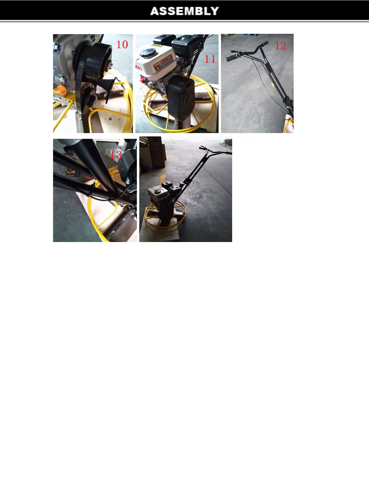
9. Put No.10 into the groove. Use No.7 bolt,spring gasket and flat gasket to fix it.
10. Install No.12 into the No.10’ belt groove.
11. Use No.1 and No.2 to fix No.15 on No.9.
12. Fix the throttle lever assembly (including in No.17) on the handle.
13. Use No.11 to strap the throttle lever assembly on the handle.
6