3
INSTALLATION AND FUNCTION EXPLANATION
3.1
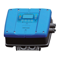
TECHNICAL DRAWING FOR INSTALLATION PROCEDURE AND INSTRUCTION
TECHNICAL DRAWING FOR INSTALLATION
PROCEDURE AND INSTRUCTION
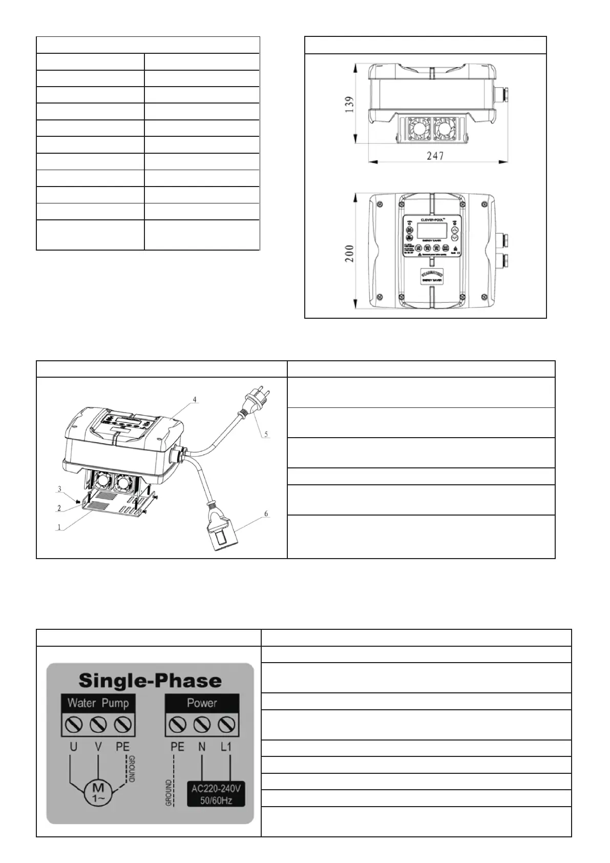
1. Use a Phillips screwdriver to take off the screws as
shown 3 and plate 1.
2. Put plate 1 at your fixing place and use screws as
shown 2 to fix the plate 1.
3. Put the control box 4 on plate 1 and fix with screws
as shown 3.
4. Put the plug from pump to the part as shown 6.
5. Put plug 5 as shown to the correct power supply
socket.
6. Strictly follow the operation steps as indicated in this
manual.
3.2
WIRE CONNECTION
Wire connection has been finished before factory delivery as per request, if you need to re-connect the wires,
please pay attention as below:
3.2.1.
WIRE CONNECTION AND DESCRIPTION FOR 2HP AC220V SINGLE PHASE IN - SINGLE PHASE OUT
PROCEDURE AND INSTRUCTION
1. Disconnect power before opening the control panel.
2. Make sure no connection between PE, N, L1
terminals and U,V terminals.
3. Wire connection operated only when power disconnected.
4. Check if the input voltage from the power supply is
compliance with CLEVER-pool.
5. No voltage duration test.
6. Screw torque for terminal screws more than 1.7Nm.
7. Ground link must be connected before operation.
8. Must use the copper wires over 1.5mm² and O dia over 8mm.
9. Power supply connected only when the control
panel is connected.
50Hz:1200~3000rpm
60Hz:1200~3600rpm