4.5 TABLE INSERT FOR DUST EXTRACTION
4.7 TILTING THE WORK TABLE
The table can be tilted to a maximum of 20°
To incline it, loosen off the locking ratchet handle FIG. 21
position B. Use the box spanner provided to turn rack and pinion
mechanism FIG. 21 position A. Turn until table is at required angle.
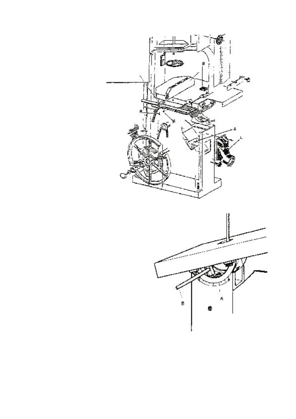
The machines are equipped with a
removable plastic insert on the work-
table, FIG.20, pos “B”, the relieved holes
of the insert improve dust extraction.
By adjusting the 4 screws at the bottom
of the opening of the work-table it is
possible to change the height of the
insert in relation to the work surface.
Models with fly-wheels up to 600 mm
diameter have one extraction outlet,
models with larger diameters have a
second outlet fitted on the base , under
the work-table ( FIG. 20, pos “
L” ).
It is recommended that the insert “ A
“ be replaced when the blade cutting
clearance widens, this will maintain
maximum efficiency of dust extraction.
4.6 CUTTING DIRECTION
AND PARALLELISM
If the cut is not perfectly parallel when
using the parallel rip fence the possible
causes are:
• Incorrect grinding and setting
of the blade
• Insufficient blade tension
• Incorrect setting of the parallel rip fence
in respect of the blade; to adjust the
parallelism of the guide, slacken, without
removing, the 2 screws “
R “, FIG. 20,
adjust the guide position and re-tighten,
firmly, the 2 screws
FIG. 20
FIG. 21