10
Fig 7.2
A
Blade Mounting and Adjustment
Before fitting the blade ensure that the machine is unplugged
from the power supply. Turn the brake off to allow manual
movement of the band wheels.
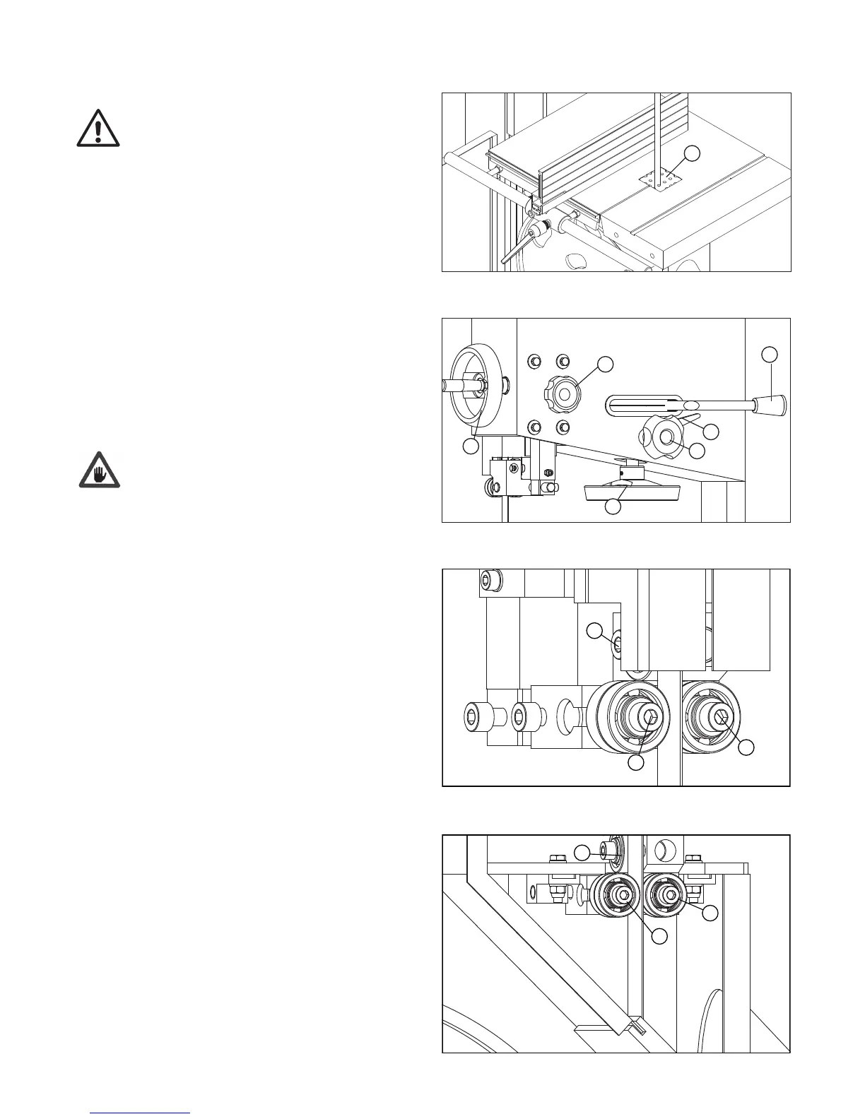
To mount the blade first remove the table insert (Fig 7.2, A) Place the
blade onto the bandwheel checking the teeth are in a correct position, and
then tighten the tension using the handwheel (Fig 7.3, A). The correct
tension value is indicated on the tension scale inside the upper door, the
indicated value corresponds to the width of the blade.
Turn the bandwheels manually, checking that the blade does not interfere
with any fixed parts and that the blade is placed correctly on the
bandwheels. The points of the teeth should slightly protrude over the edge
of the bandwheels. To adjust the blade position on the bandwheels slacken
the locking lever (Fig 7.3, B), and then turn the knob (Fig 7.3, C): the
blade will move inwards when turn the knob clockwise and the blade will
move further out when turn the knob anticlockwise; A quarter of one circle
is sufficient to make a noticeable displacement. Tighten the locking lever
after the blade is positioned correctly.
Reinstall the table insert, close the band wheels accessing doors.
After use we recommend slackening the blade tension, and to display a
visible sign on the machine advising of this procedure.
Remeber to check and re-tension before use. This operation prevents
damage to the bandwheel tyres.
Setting the Blade Guard and Guides
Adjusting the Saw Blade Guard
The adjustable saw band guard should be positioned as close as possible to
the work piece. To adjust the height, release the locking knob (Fig 7.3, D)
and turn the hand wheel (Fig 7.3, E) to move the guard up or down. Lock
the knob once the correct guard position is obtained. This operation must
always be carried out when the machine has stopped.
Roller Bearings Blade Guide
The roller bearings should be positioned as close to the blade as possible
but without touching it, to help maintain the correct cutting direction
during use. The positioning of these bearings is controlled by screw A of Fig
7.4. Once they have been adjusted, tighten screw A. They should be 2 mm
behind the teeth of the blade. The rear bearing prevents excessive backward
movement of the blade during operation and should be 1 - 2 mm from the
back of the blade. This can be adjusted using screw B of Fig 7.4.
Lower Saw Blade Guide
The roller bearings should be positioned as close to the blade as possible
but without touching it, to help maintain the correct cutting direction during
use. The positioning of these rollers is controlled by screw A of Fig 7.5.
Once adjusted, tighten screw A. They should be 2 mm behind the teeth of
the blade. The thrust shaft prevents excessive backwards movement of the
blade during operation and should be 1 - 2 mm from the back of the blade.
This can be adjusted using screw B of Fig 7.5.
CAUTION
Fig 7.3
A
B
C
D
E
F
Fig 7.5
-28-
4.4 BLADE MOUNTING AND ADJUSTMENT
- To mount blade first remove the table insert (A of FIG.4.4.1)
Place the blade onto the bandwheel checking the teeth are
in a correct position, and then tighten the tension using the
handwheel (A of FIG.4.4.2). The correct tension value is
indicated on the tension scale inside the upper door, the
indicated value corresponds to the width of the blade.
- Turn the bandwheels manually, checking that the blade does
not interfere with any fixed parts and that the blade is placed
correctly on the bandwheels. The points of the teeth should
slightly protrude over the edge of the bandwheels. To adjust the
blade position on the bandwheels slacken the locking lever( B
of FIG.4.4.2), and then turn the knob(C of FIG.4.4.2): the blade
will move inwards when turn the knob clockwise and the blade
will move further out when turn the knob anticlockwise; A quarter
of one circle is sufficient to make a noticeable displacement.
Tighten the locking lever after the blade is positioned correctly.
- Then reinstall the table insert, close the band wheels accessing
doors.
After use we recommend slackening the blade tension, and to
display a visible sign on
the machine advising of this procedure.
Remeber to check and re-tension before use. This operation
prevents damage to the bandwheel tyres.
Fig.4.4.1
A
Fig.4.4.2
A
B
C
CAUTION
4.5 SETTING BLADE GUARD & GUIDE
AJUSTING THE SAW BLADE GUARD
The adjustable saw band guard should be positioned as close
as possible to the workpiece. To adjust the height, release the
locking knob(D of Fig.4.4.2 ) and turn the handwheel (E of
Fig.4.4.2) to adjust the guard up or down. Lock the knob once
the correct position of guard is obtained.
This operation must always be carried out while the machine is
stopped.
ROLLER BEARINGS BLADE GUIDE
The roller bearings should lightly touch the blade, to prevent
vibration during operation and ensure correct direction of
cutting. The positioning of these bearings is controlled by screw
“A”(Fig.4.5.1), once they have been adjusted, tighten the screw
“A”(Fig.4.5.1); they should be 2mm behind the teeth of the
blade.The rear bearing prevents excessive backward movement
of the blade whilst in operation , and should be 1-2 mm from the
back of the blade: this can be adjusted by srew “B”(Fig.4.5.1).
LOWER SAW BLADE GUIDE
- To roller bearing should lightly touch the blade, to prevent
vibration during operation and ensure correct direction of
cutting. The positioning of these rollers is controlled by screw
“A”(Fig.4.5.2), once they have been adjusted, tighten the screw
“A”(Fig.4.5.2); they should be
2 mm behind the teeth of the
blade.The thrust shaftprevents excessive backward movement
of the blade whilst in operation , and should be 1-2 mm from the
back of the blade: this can be adjusted by srew “B”(Fig.4.5.2).
Fig.4.5.1
D
E
A
A
B
Fig.4.5.2
-28-
4.4 BLADE MOUNTING AND ADJUSTMENT
- To mount blade first remove the table insert (A of FIG.4.4.1)
Place the blade onto the bandwheel checking the teeth are
in a correct position, and then tighten the tension using the
handwheel (A of FIG.4.4.2). The correct tension value is
indicated on the tension scale inside the upper door, the
indicated value corresponds to the width of the blade.
- Turn the bandwheels manually, checking that the blade does
not interfere with any fixed parts and that the blade is placed
correctly on the bandwheels. The points of the teeth should
slightly protrude over the edge of the bandwheels. To adjust the
blade position on the bandwheels slacken the locking lever( B
of FIG.4.4.2), and then turn the knob(C of FIG.4.4.2): the blade
will move inwards when turn the knob clockwise and the blade
will move further out when turn the knob anticlockwise; A quarter
of one circle is sufficient to make a noticeable displacement.
Tighten the locking lever after the blade is positioned correctly.
- Then reinstall the table insert, close the band wheels accessing
doors.
After use we recommend slackening the blade tension, and to
display a visible sign on
the machine advising of this procedure.
Remeber to check and re-tension before use. This operation
prevents damage to the bandwheel tyres.
Fig.4.4.1
A
Fig.4.4.2
A
B
C
CAUTION
4.5 SETTING BLADE GUARD & GUIDE
AJUSTING THE SAW BLADE GUARD
The adjustable saw band guard should be positioned as close
as possible to the workpiece. To adjust the height, release the
locking knob(D of Fig.4.4.2 ) and turn the handwheel (E of
Fig.4.4.2) to adjust the guard up or down. Lock the knob once
the correct position of guard is obtained.
This operation must always be carried out while the machine is
stopped.
ROLLER BEARINGS BLADE GUIDE
The roller bearings should lightly touch the blade, to prevent
vibration during operation and ensure correct direction of
cutting. The positioning of these bearings is controlled by screw
“A”(Fig.4.5.1), once they have been adjusted, tighten the screw
“A”(Fig.4.5.1); they should be 2mm behind the teeth of the
blade.The rear bearing prevents excessive backward movement
of the blade whilst in operation , and should be 1-2 mm from the
back of the blade: this can be adjusted by srew “B”(Fig.4.5.1).
LOWER SAW BLADE GUIDE
- To roller bearing should lightly touch the blade, to prevent
vibration during operation and ensure correct direction of
cutting. The positioning of these rollers is controlled by screw
“A”(Fig.4.5.2), once they have been adjusted, tighten the screw
“A”(Fig.4.5.2); they should be
2 mm behind the teeth of the
blade.The thrust shaftprevents excessive backward movement
of the blade whilst in operation , and should be 1-2 mm from the
back of the blade: this can be adjusted by srew “B”(Fig.4.5.2).
Fig.4.5.1
D
E
7. Installation and Operation
 Loading...