11
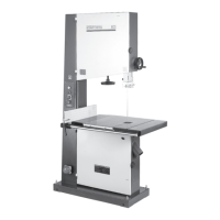
Fig 7.6
A
B
C
D
Tilting The Work Table of the 403 and 503
The table may be set at 90º to the blade by adjusting the table stop screw
beneath the table. The table stop screw rests on the top of the lower
wheel bandwheel housing. By first slackening the locking nut A of Fig 7.6
and then adjusting the screw B of Fig 7.6, the table can be set correctly.
Retighten the locking nut A making sure that the setting is maintained.
To make adjustments of table tilting, slackening the locking handle D of Fig
7.6 and rotate the shaft C of Fig 7.6 with the special handle found in the
loose parts bag supplied with the machine. When adjustment is complete,
tighten the handle D of Fig 7.6 to lock it.
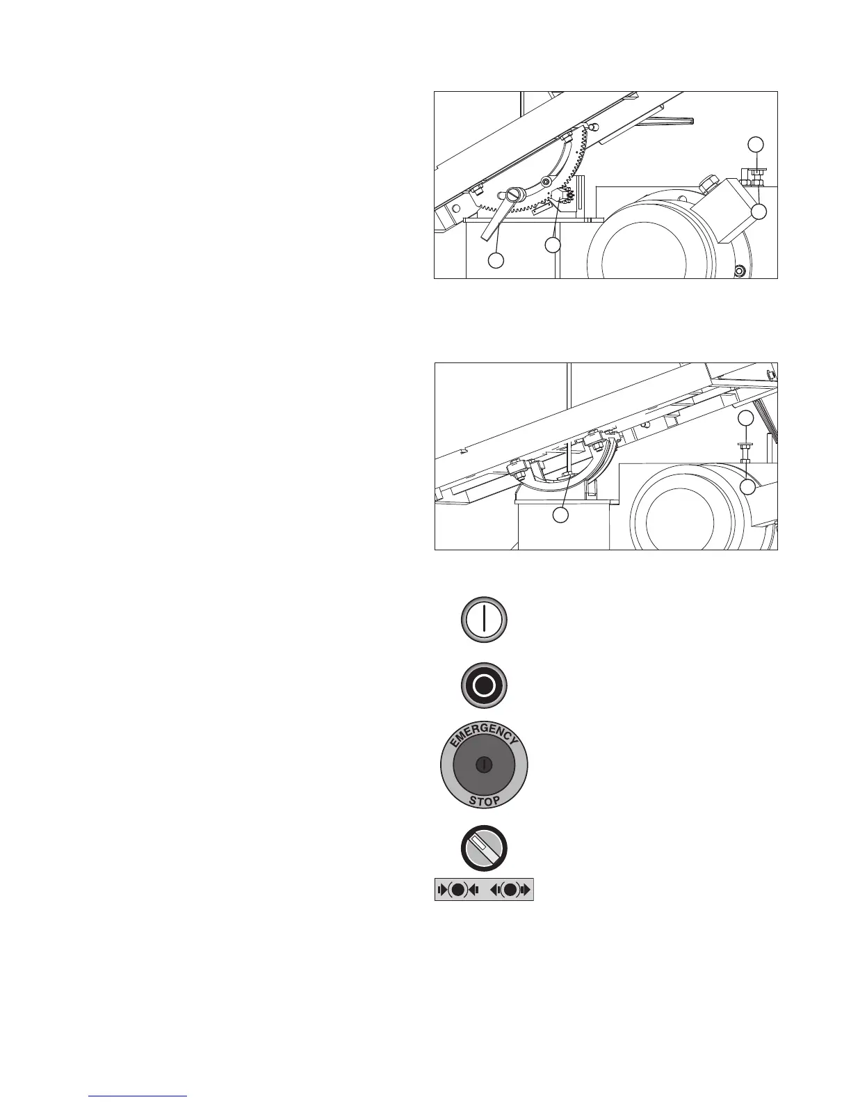
Tilting the Work Table of the 603
The table may be set at 90º to the blade by adjusting the table stop screw
beneath the table. The table stop screw rests on the top of the lower
wheel bandwheel housing. By first slackening the locking nut A of Fig 7.7
and then adjusting the screw B of Fig 7.7, the table can be set correctly.
Retighten the locking nut A making sure that the setting is maintained.
To make adjustments of table tilting, slackening bolt C of Fig 7.7. When
adjustment is correctly finished, tighten the handle D of Fig 7.7 to lock it.
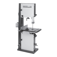
Operating the Bandsaw
Before attempting to start the bandsaw ensure the emergency stop switch
is not in the depressed position. If necessary, unlock the switch with the key.
Ensure the brake switch is in the ON position as shown in Fig 7.8 then
press the on button.
To stop the bandsaw press either the off button or the emergency stop
button.
If the bandsaw is stopped using the emergency stop button the key must be
used to unlock it from the depressed position.
Prevention of Unauthorised Use
To prevent the bandsaw being used without authorisation, depress the
emergency stop button and remove the key.
On button
Off button
Emergency stop button
Brake switch
Fig 7.7
Fig 7.8
C
B
A
7. Installation and Operation