6. Braking System
The machines are equipped with an electro-magnetic brake that
ensure stopping all moving parts within 10 seconds,
The brake pads of the braking system are subject to wear, it
is recommended that they are checked regularly and replaced
when necessary, to maintain the braking time within regulations
fixed by the norms.
6.1 MAINTENANCE AND ADJUSTMENT OF
THE BRAKING SYSTEM
REPLACING THE BRAKE LININGS
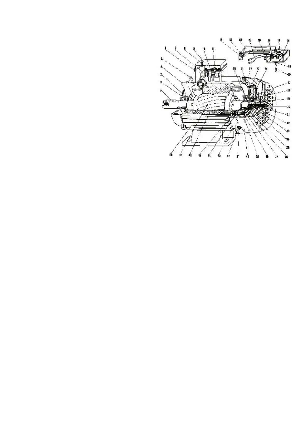
Remove the fan cover (
40) and unscrew the self-locking nut
(31), pull out thecooling and braking fan (34) On the mobile
anchor (
28) of the brake you will find the lining. Pull the old lining
off and, with clean hands, glue the new one on. To re-assembly
the parts, please follow directions in reversed order and type of
operations.
BRAKE UNIT REPLACEMENT
Take the fan cover (
40) off and unscrew the self locking nut (31)
pull out the cooling and braking fan (
34), the thrust linings (24)
and the thrust spring (
27). At this point, you should isolate the
rectifier diode by disconnecting the cables (the diode can be
found either in position (
44) or in the terminal box position 18).
Unscrew the 3 allen screws (
23), change the brake unit and
repeat the operations in reverse to fit the other parts.
ADJUSTMENT OF THE BRAKING AIR-GAP
The machine will stop between 6 and 10 seconds maximum. By
turning the self locking nut of the brake control (
31) it is possible
to vary the braking time from 6 to 10 seconds. It is extremely
important that after this operation a gap of 0.5 mm remains
between the mobile anchor and the brake unit. The air gap is the
distance between the mobile anchor and the brake unit.
MANUAL OPERATION TO RELEASE THE BRAKE
Unscrew the self locking nut (
31) until the cast iron fan moves
away from the mobile anchor (
28) beyond the widest possible
air gap. This allen screw also allows to check the air gap back to
the original distance after the wearing out of the brake linings.