The Stat-X® Dual Release Panel (SDRP), Part No. 830001, is a sophisticated automatic fire detection and releasing control panel designed for use with Stat-X generators. It provides automatic fire detection and manual actuation capabilities for up to four (4) Stat-X generators without the need for direct power connection, utilizing replaceable internal lithium batteries that supply power for up to three (3) years in service, even after discharge. The SDRP is specifically designed for rugged commercial and off-road vehicle use, with detection and release zones configured for either dual detection zones and dual releasing zones, or individual separate actuation zones.
Function Description:
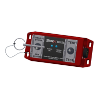
The SDRP provides automatic fire detection and actuation of Stat-X generators. It includes two detection zones and two releasing zones, allowing for flexible programming configurations. The panel features electrical supervision of fire detection, release, and manual actuation circuits. It incorporates a maintenance/transport guarded toggle switch that can be secured in the "Disarm System" position to prevent unwanted discharge during transport or vehicle maintenance. A second momentary action guarded toggle switch performs an on-command system test of circuit integrity and battery condition. When commanded, the test switch illuminates a built-in test of the fire suppression system, with a green "System OK" LED indicating proper function and a yellow "System Trouble" LED indicating an issue. The SDRP operates using Class B detection as defined by NFPA 72 National Fire Alarm and Signaling Code, employing normally open sensors wired in parallel for thermal detection. Electrical supervision of detectors and wiring is provided via a 470k ohm end-of-line resistor. If a wiring break is detected, a "Trouble" condition is displayed. If a wiring or thermal detector closure occurs, the SDRP automatically actuates the connected Stat-X generators.
Important Technical Specifications:
- Power Source: Replaceable internal lithium batteries (replace after 3 years or following a system discharge).
- Detection Zones: Two (2) detection zones.
- Releasing Zones: Two (2) releasing zones.
- Generator Capacity: Up to four (4) Stat-X generators.
- Detection Type: Class B detection (NFPA 72 National Fire Alarm and Signaling Code).
- End-of-Line Resistor: 470k ohm (PN 830007).
- Detection Zone Wiring: UL listed Plenum cable, 18 AWG, solid annealed bare copper. Maximum 100 detectors per detection zone. Maximum total wiring length 500 feet (152 meters).
- Actuation Zone Wiring: UL listed Plenum cable, 18 AWG, solid annealed bare copper. Maximum 2 generators per actuation zone. Maximum total wiring length 100 feet (30 meters).
- Environmental Sealing: IP67 standard for the Manual Release Switch (PN 830003).
- Connectors: MIL-26482 metal shell connectors for field wiring.
- Thermal Detection: Linear Thermal Wire (various part numbers) with alarm temperature ratings of 135°F, 155°F, 190°F, 220°F, 280°F, and 356°F. Spot Thermal Sensors (various part numbers) with alarm temperature ratings of 135°F and 194°F, available for various environments including Vertical Interior, Vertical All Weather, Vertical 1½" Conduit, and Explosion Proof.
Usage Features:
- Control Panel Location: Must be located where periodic testing and maintenance can be performed, with accessible and visible toggle switches and LED display. Should be protected from water, oil, conductive materials, and high temperatures.
- Manual Release Switch (PN 830003): Provides a manual means of actuation. Must be located in an accessible location in the path of egress, between 42" and 48" above the floor. Protected by a labeled and latching toggle guard and stainless steel protective bracket. Electrically supervised by the SDRP for Normal, Trouble, and Fire conditions.
- System Status Indicators: Green "System OK" LED (illuminates when test toggle is flipped and system is OK) and yellow "System Trouble" LED (illuminates when test toggle is flipped and a problem exists).
- Disable-Arm Toggle Switch: Used to disarm the system for maintenance or transport, preventing accidental discharge.
- Manual Test Switch: Allows for on-command testing of circuit integrity and battery condition without actuating the generators.
- Wiring: Field wiring for detection and actuation zones must be UL listed Plenum cable, 18 AWG, solid annealed bare copper. Connections must be clean, mechanically secure, and free from moisture and corrosion. Actuation wiring must be located away from and protected from potential hazard areas.
Maintenance Features:
- Battery Replacement: Batteries must be replaced every three years or following a system discharge. The panel is designed for easy access to mounting hardware for battery replacement.
- Daily Inspection (if possible): With the panel in "Armed" mode, flip the test toggle switch. The "System OK" LED should appear green. If not, or if the "System Trouble" LED appears yellow, troubleshoot the system. If no LEDs are on, troubleshoot.
- Monthly Inspection:
- Visually inspect field wiring for damage or changes.
- Check automatic detection circuit for damage or changes.
- Verify spot thermal detectors or linear thermal wire are not painted, damaged, or blocked.
- Check Stat-X actuation wiring for damage, contact corrosion, or changes.
- Check detection circuit end-of-line device for damage or changes.
- Check Manual Release Switch for damage or changes.
- Annual Inspection:
- Attach alarm module PN 830002 to both SDRP actuation circuits before testing.
- Verify "System OK" operation by flipping the test toggle switch.
- Spot Thermal Detection Test: Use a heat gun to heat each spot thermal sensor to its alarm set point, verifying with a thermocouple. Each alarm module should latch in a "fire" condition. Allow sensors to cool, then press "System Reset" on the alarm module to clear the alarm.
- Linear Thermal Detection Test: Linear thermal detection wiring cannot be tested with a heat gun. Remove the PN 830007 EOL device and replace it with a PN 830003 manual test switch. Flip the manual test switch to simulate an alarm condition. Each alarm module should latch in a "fire" condition. Return the manual test switch to normal operation, then press "System Reset" on each alarm module to clear the alarm.
- Continue testing remaining linear detection circuits.
- Replace internal batteries every three years or following any system discharge.
- Remove alarm modules.
- Reconnect Stat-X generators.
- Perform a final test by toggling the "TEST" switch; the "System OK" LED should appear green.
- Record replacement date on the supplied label and attach it to the control panel.
- Troubleshooting Guide: The manual provides a comprehensive troubleshooting table for various fault conditions (e.g., detection field wiring problem, actuation field wiring problem, manual release switch problem, disable switch position, internal battery problem) with possible open conditions and recommended checks.