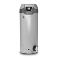
Do you have a question about the State Water Heaters 60120-100250 and is the answer not in the manual?
| Category | Water Heater |
|---|---|
| Brand | State Water Heaters |
| Model Number | 60120-100250 |
| Type | Electric |
| Energy Source | Electric |
| Voltage | 240 V |
Details required qualifications for installation and service personnel.
Advises against performing procedures if not qualified or licensed by jurisdiction.
Lists essential tools for servicing the water heater.
Emphasizes the importance of meeting combustion and ventilation air requirements.
Discusses how contaminated air can damage components and cause product failure.
Provides an exploded view and identification of blower and burner components.
Illustrates the top view of components for specific models.
Describes the fault condition of insufficient gas pressure and its causes.
Details the required gas supply pressure specifications for different models.
Explains the requirements and installation of gas supply regulators.
Provides a procedure for testing gas supply pressure.
Identifies and describes the function of pressure switches.
Outlines procedures for testing pressure switch continuity and operation.
Lists the activation pressures and tolerances for pressure switches.
Details how to test for flame presence during ignition cycles.
Addresses troubleshooting steps when the burner fails to ignite.
Explains the function and operation of the gas control valve.
Provides procedures for testing voltage to the gas control valve.
Explains the principle of flame sensing current.
Details how to measure flame sensing current.
Describes the function and monitoring of powered anodes.
Provides step-by-step instructions for anode maintenance.
Introduces the temperature probe, ECO, and sensor components.
Outlines how to test the temperature sensor resistance.
Covers general venting requirements for Category IV appliances.
Specifies the importance of correct intake air and vent piping size.
Details the procedure for connecting the 120 VAC power supply.
Explains the function and operation of the Enable/Disable switch.
Explains the fundamental operation and construction of the water heater.
Describes the combustion blower assembly and its control.
Explains how the CCB modulates the firing rate for temperature control.
Provides step-by-step instructions for removing the blower and burner assembly.
Provides step-by-step instructions for installing the blower and burner assembly.
Identifies pinout for high voltage input to the CCB.
Identifies pinout for blower logic and VFD signals.
Identifies pinout for 120V output from the CCB.
Identifies pinout for the temperature probe connection.
Identifies pinout for limit switches and sensors.
Identifies pinout for pressure switch connections.
Describes the UIM display, buttons, and status icons for user interaction.



 Loading...