Do you have a question about the State Water Heaters SHE 50-100 NE and is the answer not in the manual?
| Category | Water Heater |
|---|---|
| Brand | State Water Heaters |
| Model | SHE 50-100 NE |
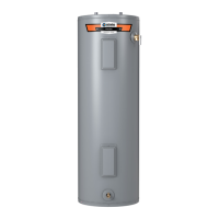
| Type | Electric |
| Capacity | 50 gallons |
| Voltage | 240 V |
| Phase | 1 |
| Wattage | 4500 W |
| Energy Factor | 0.93 |
| Warranty | 6 years |
| Inlet/Outlet Size | 3/4" |
| Recovery Rate | 21 gallons per hour at 90°F rise |
Details the qualifications required for installing and servicing water heaters, emphasizing agency and skill equivalency.
Provides a crucial warning against performing tasks without proper qualifications or understanding of the manual's procedures.
Emphasizes visual inspection of wiring and connectors before component replacement for reliable service.
Lists essential tools for water heater installation and service, including specific wrenches and meters.
Highlights the importance of having the original manual for model-specific installation and service information.
Explains how devices like pressure reducing valves create closed systems affecting water volume.
Discusses water expansion when heated, potential tank failure, and TPR valve operation.
Highlights the necessity of adequate combustion and ventilation air for proper operation and preventing issues.
Warns about aerosols, chemicals, and vapors damaging components and causing product failure.
Covers Category IV appliance equivalence, power vent, and direct vent configurations for heaters.
Describes appliances operating with positive vent pressure and low vent gas temperatures producing condensate.
Explains how power vent systems draw combustion air from the room and vent exhaust through a single pipe.
Details direct vent systems using sealed intake and exhaust pipes for combustion and venting.
Provides guidelines for calculating total pipe length including elbows for intake and vent pipes.
Specifies when 2-inch or 3-inch pipe must be used based on equivalent length and elbow count.
States the maximum number of 90° elbows allowed for vent and intake air pipes.
Stresses the critical need for correct grounding and power supply polarity to prevent faults.
Details how to verify proper grounding and polarity using a voltmeter or outlet tester.
Describes the factory-installed screen and hose barb on the intake air connection and their importance.
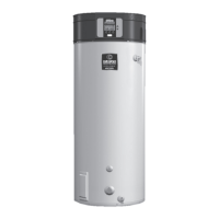
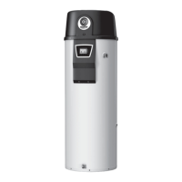
Identifies external components like the UIM, drain valve, and TPR valve on the front and back of the water heater.
Illustrates and labels components on the top of the water heater, including the combustion blower and CCB enclosure.
Provides exploded and assembled views of the combustion blower and burner, detailing key parts like igniter and flame sensor.
Explains the water heater's internal operation, including the helical heat exchanger and forced draft burner.
Describes the function and control of the combustion blower assembly, including its speed control.
Details the radial design burner, its components, and its role in the combustion process.
Provides step-by-step instructions for safely removing and inspecting the combustion blower and burner assembly.
Explains the flame sensing operation principle and its importance for ignition proofing.
Outlines the procedure to measure flame sensing current using a DC micro amp meter for troubleshooting.
Describes the hot surface igniter (HSI), its function, and factors affecting its life.
Details how to test igniter amperage to ensure it's sufficient for ignition.
Explains the Venturi's role in mixing combustion air and fuel gas, creating negative pressure for gas draw.
Describes the 24 Volt DC gas valve, its AC to DC rectification, and voltage tests.
Details checks for 24 VAC supply to the valve and 24 VDC at the plug end.
Provides instructions for removing the gas valve, including inspecting the gas orifice.
Explains manifold offset and supply gas pressures and their importance for proper operation.
Outlines the procedure for measuring gas pressures using digital manometers.
Illustrates pressure changes during different operating states to verify gas flow and valve operation.
Describes the construction, operation, and types of the three pressure switches.
Explains how the control system monitors pressure switches and potential fault messages.
Details continuity and pressure tests for pressure switches during standby and operation.
Describes the temperature probe, including the ECO limit switch and temperature sensor.
Provides steps to test the continuity of the ECO switch for proper reset.
Introduces the main control system components: UIM and CCB.
Details the UIM's components, including the LCD and user input buttons.
Explains the correct method for connecting the ribbon cable to the UIM circuit board.
Describes the CCB as the main control board managing ignition and temperature.
Provides instructions for safely removing and reinstalling the CCB enclosure cover.
Details the layout of the CCB, including socket connectors and dipswitch functions.
Lists and describes the pin assignments for various CCB sockets.
Presents a comprehensive wiring diagram of the water heater's electrical system.
Explains control system features, navigation, status icons, and diagnostics.
Differentiates control system operation and settings for commercial vs. residential models.
Describes the meaning of various animated icons displayed on the UIM screen.
Lists and explains the common operational states of the control system.
Outlines the different menus accessible through the control system for settings and information.
Covers adjustment of Operating Set Point and Differential for temperature control.
Displays real-time status of components like blowers, igniters, and pressure switches.
Allows adjustment of temperature units, backlight delay, and screen contrast.
Provides operational data like elapsed time, burner run time, and cycle count.
Shows the active fault or alert message with a brief description and advanced details.
Lists the last nine fault and alert messages with timestamps for historical analysis.
Tracks the total count of each fault condition since installation.
Option to reset user-adjustable settings to their original factory configurations.
Allows entry of service provider contact details to be displayed with fault messages.
Details the step-by-step process the control system follows during a heating cycle.
Visual representation of the control system's sequence of operation and fault logic.
Provides guidance for common fault conditions, checks, and repairs.
Addresses issues where the UIM display is blank or input buttons do not respond.
Lists and explains various fault messages detected by the control system.