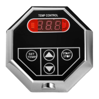
Model: TC-110
Steambath Control
WARNING: Elderly persons, pregnant women, or those suffering from heart disease, high blood
pressure, diabetes, or who are otherwise not in good health, do not use this device unless
directed to do so by a physician. Also, do not use steambath while under the influence of alcohol.
!
07/07
Pub. No. 526-D
C
US
®
LISTED 995C
Installation and Operating Instructions
TC-110
NOTE: This control may be installed inside or outside the
steam room for operation of the system.
Start/Stop Key Pad: Press key pad and generator will
begin producing steam in minutes. The generator will
remain on for 30 minutes when used with the model
SM-46, SM-79 SM-4, SM-5, SM-7, or SM-8 steam
generators and 60 minutes for larger generators.
Pressing the key pad a second time will stop the
Steam Generator.
Start/Stop Light: Indicates the Steam Generator is
activated.
Cleaning Instructions: Use a damp cloth and mild soap.
Do NOT use abrasive cleaners which might scratch the
surface or the base of the control.
- 1 -
Control Features
Installation Instructions
The TC-110 control may be installed inside or
outside the steam room. For convenience the
recommended height from the floor is four feet.
Provide a 1” hole in the wall at this location (see
Figure 1).
IMPORTANT: Multi-conductor cable must be
installed so that the end will not be buried inside the
wall. The unit will not operate unless the control is
installed.
1. Pre-Installation - Control Location
a)
Remove the multi-conductor cable from the control
packing box. Carefully route the multi-conductor
control cable from the Steambath Generator to the
TC-110 located either inside or outside the
steamroom (see Figure 2). Route multi-conductor
cable though a ¾” conduit to protect the cable from
damage and to facilitate replacement if necessary.
2. Electrical Rough-in
a)
IMPORTANT: The TC-110 Control will only function with one of the following Steamist Generator models:
SM-46, SM-79, SM-4, SM-5, SM-7, SM-8, SM-11, SM-12, and SM-15. (It will not work with Models:
System-18, System-24, & System-30 unless used in cunjuction with a Steamist thermostatic controller, such
as Model# TC-135 or DSC-425).
START
STOP
1.
2.
Timer and Start/Stop Switch
1“ Hole
located four feet
from the floor
Double-sided
Adhesive Pad
TC-110 Timer and
Start/Stop Switch
Figure 1
IMPORTANT: Run the
Control Cable through a
¾” conduit.
2
1