EasyManua.ls Logo

Steamist TSC-250 - User Manual

Steamist TSC-250
4 pages
Print Icon
To Next Page IconTo Next Page
Loading...
1½“ Hole
located four feet
from the floor
Double-Sided
Adhesive Pad
IMPORTANT: Run the
Control Cable through
a ¾” conduit.
Coupler
To Steam Generator
4
1
21
TIME
TEMP
IM
STOP
3
2
6
5
7
C
US
®
WARNING: Elderly persons, pregnant women, or those suffering from heart disease, high blood pressure, diabetes, or
who are otherwise not in good health, do not use this device unless directed to do so by a physician. Also, do not use
steambath while under the influence of alcohol. For additional Important Safety Information, please see a separate
instruction sheet Pub. No. 199.
!
IMPORTANT: The TSC-250 Control will only function with the current TSG steam generators.
Installation and Operating Instructions
Steambath Control
Installation Instructions
Model: TSC-250
Control Features
1. Display: The digital read out displays the ambient tempera-
ture, set point and remaining time in minutes. It is also used
to display diagnostic error codes.
2. Steam Icon: When illuminated the steam cycle is running.
3. Water Icon: When steam shower is not in use the blue water
waves indicate the InstaMist feature is on. This is also
illuminated when the steam bath cycle is running.
4. Time / Temp button: Used to program the default timer when
the steam bath is off. Adjustments are made with the
Up/Down buttons. The button will switch between time and
temperature when the steam bath is on. Adjustments to the
timer made during a steam bath cycle are temporary. All
temperature adjustments are held in memory for the user of
the cycle that is running.
5. IM/Stop button: Toggles the InstaMist feature on/off when
the steam bath is off and stops the steam bath cycle when a
cycle is started. InstaMist is a preheat function that keeps the
water heated for quick starts.
6. User 1 button: Starts the user one cycle and is the up
function while in cycle.
7. User 2 button: Starts the user two cycle and is the down
function while in cycle.
1. Pre-Installation - Control Location
a) The TSC-250 Control must be installed inside the steam
room. For convenience the recommended height from
the floor is four feet. Provide a 1½" hole in the wall at
this location (see Figure 1).
IMPORTANT: Multi-conductor cable must be installed so
that the end will not be buried inside the wall. The unit
will not operate unless the control is installed.
2. Electrical Rough-in
a) Remove the multi-conductor cable from the control
packing box. Carefully route the multi-conductor control
cable from the steam generator to the TSC-250 located
inside the steamroom (see Figure 2). Route multi-
conductor cable through a ¾" conduit to protect the
cable from damage and to facilitate replacement if
necessary.
TSC-250 Digital Temperature Control
Figure 1
06/10
Pub. No. 271-A
- 1 -
IMPORTANT: This control must be installed inside the
steam room for proper operation of the system.
Cleaning Instructions: Use a damp cloth and mild soap.
Do NOT use abrasive cleaners which might scratch the
surface or the base of the control.
Inside Installation:
TSC-250 Control.
Locate away from
the direct line of
shower spray and
do NOT locate
above steamhead.
®

Other manuals for Steamist TSC-250

Question and Answer IconNeed help?

Do you have a question about the Steamist TSC-250 and is the answer not in the manual?

Summary

Steambath Control Features

Digital Display Functions

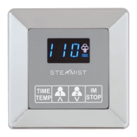
Displays ambient temperature, set point, remaining time, and diagnostic error codes.

Steam Cycle Indicator

Illuminates when the steam cycle is running.

InstaMist Feature Indicator

Illuminated when InstaMist feature is on or steam bath cycle is running.

Time and Temperature Programming Button

Programs default timer and switches between time/temperature display.

InstaMist and Stop Button

Toggles InstaMist feature or stops the steam bath cycle.

User 1 Cycle and Up Function

Starts User 1 cycle and acts as the up function during a cycle.

User 2 Cycle and Down Function

Starts User 2 cycle and acts as the down function during a cycle.

Control Location and Electrical Rough-in

Control Unit Mounting Location

Install inside steam room, four feet from floor, requiring a 1½" hole.

Multi-Conductor Cable Routing

Route multi-conductor cable through a 3½" conduit to protect it from damage.

Important Safety Information and Compatibility

Health Precautions for Use

Advises consulting a physician for certain health conditions and avoiding alcohol use.

Generator Compatibility

The TSC-250 Control only functions with current TSG steam generators.

Control and Cable Installation Details

Connecting Control Cable and Mounting

Route cable, connect modular jack, and adhere control to wall with silicone seal.

Watertight Seal Requirement

Installer must seal control with silicone; water damage not covered by warranty.

Steamhead and Center Hub Installation

Nipple Protrusion for Steamhead

Ensure 3/4" nipple protrudes approximately 1/2" beyond the tile for proper seal.

Nipple Sealant Tape Application

Apply pipe sealant tape to the 3/4" nipple before installation.

Back Plate and Center Hub Assembly

Center Back Plate over pipe, then screw Center Hub onto nipple using Hex Key.

Center Hub Alignment and O-Ring Seal

Align Center Hub and ensure O-ring is seated for proper seal.

Cover Plate Attachment

Apply silicone to Cover Plate, hook top, and snap bottom into place.

Operating Instructions

Starting and Cancelling Cycles

Press USER 1 or USER 2 to start, press STOP to cancel.

Time and Temperature Adjustment

Toggle TIME/TEMP to select and adjust temperature or remaining time.

InstaMist Feature Operation

Press IM keypad to activate InstaMist for faster heat-up.

Programming and Memory Functions

Temperature and Time Memory

Set points and default time retained even after power failure.

Programming User Cycles

Adjustments made while a cycle is active are saved for that user.

Default Time Programming

Program default time when cycle is off by pressing TIME/TEMP.

Service and Error Modes

Entering Service Mode

Press and hold TIME/TEMP button in Off mode for 3 seconds.

Service Mode Functions

Change F/C setting, reset factory defaults, or display program version.

Error Code Interpretation

Flashing 'Er' codes indicate internal control or communication issues.

Installation Suggestions

Steamhead Mounting Height

Mount steamhead 18" above floor or 6" above tub rim, away from bather.

Control Unit Location

Locate inside control away from direct spray and not above steamhead.

Steamist TSC-250 Specifications

General IconGeneral
ModelTSC-250
TypeControl Panel
DisplayDigital
Steam Output ControlYes
Temperature ControlYes
TimerYes
Water Level IndicatorYes
MountingWall-mounted
MaterialPlastic
ColorWhite

Related product manuals