Do you have a question about the Steca Solsum F and is the answer not in the manual?
General safety guidelines for PV systems, handling batteries, and avoiding hazardous environments.
Monitors battery state of charge, controls charging and load connection/disconnection for optimal battery use.
Guidelines for selecting a suitable mounting location, avoiding moisture, heat, and ensuring ventilation.
Instructions for physically mounting the controller to a wall using screws and dowels.
Details on wiring the controller, including cable size, fuses, and connection sequence.
Explains the meaning of different LED statuses for normal operation, faults, and battery levels.
Information on system grounding and national regulations regarding protective low voltage circuits.
Advises on installing additional protection for systems at increased risk of overvoltage damage.
Outlines the maintenance-free nature of the controller and annual PV system checks.
Lists common issues like no display or battery not charging and their potential causes.
Detailed technical specifications and operating parameters for different models of the controller.
The Steca Solsum F-Line is a solar charge controller designed for use in stand-alone photovoltaic (PV) systems. It serves as a crucial component in managing the charging process of lead-acid batteries and controlling the connection and disconnection of loads, thereby optimizing battery usage and extending its service life. This controller is suitable for system sizes up to a maximum of 240 W, operating at automatically recognized 12 V or 24 V with a power range of up to 10 A.
The primary function of the Steca Solsum F-Line is to regulate the charging of lead-acid batteries from solar panels. It employs Pulse Width Modulation (PWM) as a low-loss series controller, which is a highly efficient method for battery charging. The controller features multistage charging technology, ensuring that the battery receives optimal charging at different stages of its charge cycle. This includes a boost charge stage to quickly bring the battery to a higher state of charge and an end-of-charge voltage to prevent overcharging.
A key aspect of its functionality is its comprehensive electronic protection. The device is equipped with overcharge protection, preventing damage to the battery from excessive charging. Deep discharge protection safeguards the battery from being discharged too low, which can significantly reduce its lifespan. Reverse polarity protection is implemented for the module, load, and battery, offering crucial safety against incorrect wiring. An automatic electronic fuse provides protection against short circuits in both the load and module. Overvoltage protection at the module input prevents damage from excessively high voltages from the solar panels. The controller also includes open circuit protection without a battery, reverse current protection at night to prevent battery discharge back into the solar panels, and overtemperature and overload protection to ensure safe operation under various conditions. A battery overvoltage shutdown further enhances safety.
The Steca Solsum F-Line also manages the connection and disconnection of loads. It features current-compensated load disconnection and automatic load reconnection, ensuring that loads are disconnected when the battery reaches a low state of charge (deep discharge protection) and reconnected when the battery has sufficiently recovered. Temperature compensation is integrated to adjust charging parameters based on ambient temperature, optimizing battery performance and longevity. The controller supports common positive grounding or negative grounding on one terminal, offering flexibility in system design. Additionally, it provides a monthly maintenance charge, which helps to keep the battery in good condition during periods of low usage.
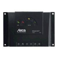
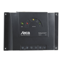
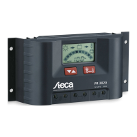
The Steca Solsum F-Line is designed for ease of use and installation. Its compact and robust design allows for upright mounting on a non-flammable substrate, such as a concrete wall. Large terminals are provided to facilitate a simple and secure connection of solar panels, battery, and load cables. The device's user interface is straightforward, featuring a multifunction LED display with multi-coloured LEDs. These LEDs clearly indicate various operating states, including normal operation, state of charge, and fault messages. This visual feedback makes it easy for users to monitor the system's status at a glance.
The controller's automatic detection of voltage (12 V or 24 V) simplifies setup, as it automatically adapts to the system's battery voltage. For enhanced control and customization, the Steca PA RC 100 remote control can be used. This remote allows for the pre-setting of a night light function in the factory or its adjustment by the user. It also enables the parameterization of various function values, offering flexibility to tailor the controller's behavior to specific application needs. The device is designed to be installed as close as possible to the batteries, with a recommended safety clearance, to ensure optimal performance. The installation process is clearly outlined, emphasizing the correct sequence of connections to ensure safety and proper functioning.
The Steca Solsum F-Line is designed to be maintenance-free, minimizing the need for regular intervention by the user. However, general maintenance practices for the overall PV system are recommended to ensure long-term reliability. The manual advises checking all components of the PV system at least annually, in accordance with the specifications of their respective manufacturers.
Key maintenance checks include ensuring adequate ventilation of the cooling element to prevent overheating. Users should also check the cable strain relief to ensure all cables are securely fastened and not under undue stress. All cable connections should be checked for security, and screws should be tightened if necessary to prevent loose connections. Finally, checking for corrosion on terminals is important to maintain good electrical contact and prevent performance degradation. The robust electronic protection functions of the controller also contribute to its low maintenance profile by preventing common faults and damage that would otherwise require repair. The device's compliance with European Standards (CE) and RoHS, along with its development in Germany and manufacturing according to ISO 9001 and ISO 14001, attest to its quality and reliability, further reducing the need for extensive maintenance.
| Max. cable cross-section | 4 mm² |
|---|---|
| System voltage | 12/24 V |
| Rated solar current | 10A |
| Self-consumption | < 4 mA |
| Max. charging current | 10 A |
| Max. load current | 10 A |
| Protection | Reverse polarity |