Do you have a question about the Steca TR A301 and is the answer not in the manual?
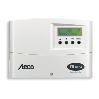
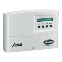
Details the correct and intended use of the temperature difference controller within permissible ambient conditions.
Outlines critical safety hazards during installation, connection, and operation, including electrocution and fire risks.
General instructions for the physical installation and mounting of the controller, including warnings about damp environments and drilling precautions.
Covers essential steps and precautions for wiring the controller to power and sensors, including cable feed preparation and connection methods.
Step-by-step guide to test the pump operation after installation, including connecting mains supply and setting the operating switch.
Explains the core logic for pump activation based on temperature differentials between collector and storage tank.
Describes the function preventing the storage tank from overheating by stopping charging.
Details the protection mechanism against excessive collector temperatures, stopping the pump to prevent fluid evaporation.
Helps diagnose and resolve common issues encountered with the controller and system, such as blank display or pump malfunction.
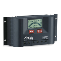
| Type | Solar charge controller |
|---|---|
| Rated Current | 30 A |
| Temperature Compensation | Yes |
| Application | Off-grid solar systems |
| PWM output | Yes |
| Data logging | No |
| Enclosure protection | IP 32 |
| Max. load current | 30 A |
| Nominal Voltage | 12 V / 24 V (automatic detection) |
| Display | LCD |
| Inputs | PV |
| Outputs | Battery Output, Load Output |
| Battery type | Lead Acid, Gel, AGM |
| Protection features | Overload, short circuit, deep discharge, reverse polarity |
| Operating temperature range | -20 to +50 °C |