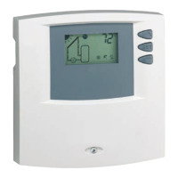
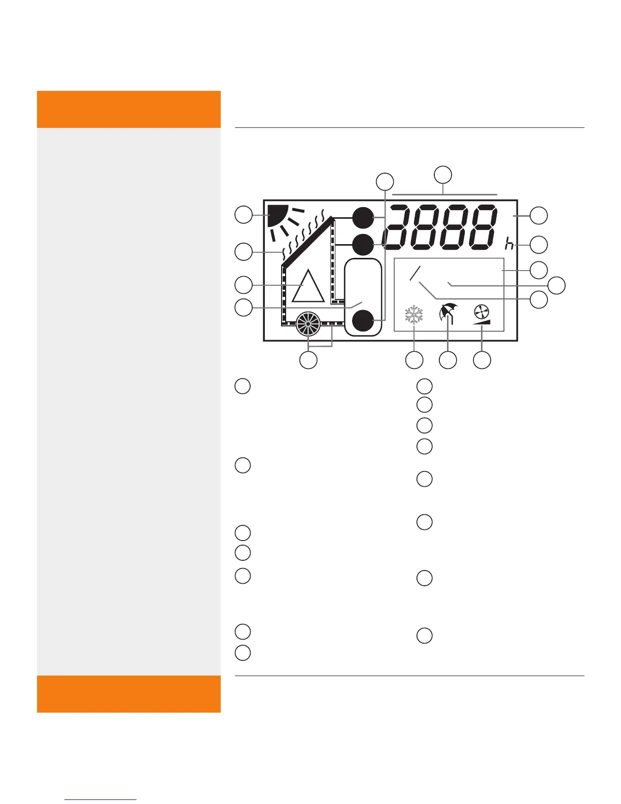
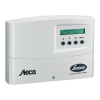
1
Temperature sensor symbols
Top T1 = collector sensor
Bottom T1 = sensor for tube
collector function
T2 = sensor for lower area of
storage tank
2
Display for temperature values,
operating hours and fault
symbols, e.g. short circuit, inter-
ruption (see page 40) or "SYS" =
system error (see page 41)
3
Display for temperature unit °C / °F
4
ECM pump operating hours
5
Setting the maximum storage
tank temperature (max) and
display of min/max temperature
values
6
Tube collector function
7
Setting the temperature unit °C / °F
8
Speed control
9
Holiday function (see page 35)
10
Anti-freeze function (see page 34)
11
Symbols for pump operation and
heat transfer fluid circulation
12
Display for "Maximum storage
tank temperature has been
reached"
13
Warning sign in the case of a
fault e.g. short circuit, interrup-
tion (see page 40) or "SYS" =
system error (see page 41)
14
Display when the maximum
collector temperature is reached,
means possible evaporation of
the collector fluid
15
Display when the switch-on tem-
perature difference is reached,
means "sufficient heat available"
15
14
13
12
11
1
9
3
4
810
5
6
7