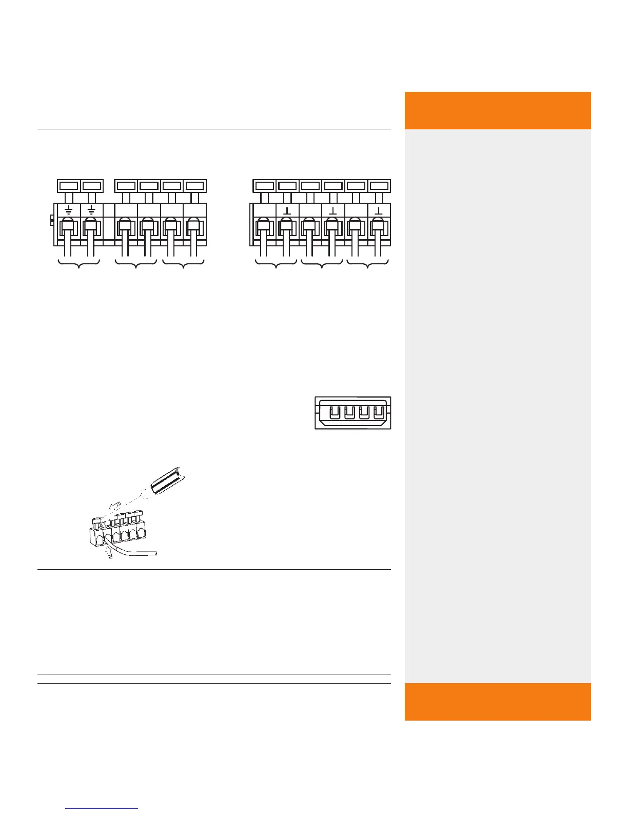
4.3.3 Terminal plan
Protective
conductor
PWM control signal
for ECM pump
Temperature sensor 1
(collector)
Grid
230 V~
Power supply for the ECM
pump
230 V~
ATTENTION: Voltage always
present!
Temp
erature sensor 2
(lower area of storage tank)
4.3.4 Actuating the connecting terminals
NOTE
The connecting terminal may only be actuated with
an appropriate tool. An unsuitable tool or too much
mechanical pressure can damage or even destroy the
connecting terminal.
Optional:
Grundfos Direct
Sensors
TM
VFS 1-12