15
738.955 | 10.40
EN
Each terminal may only be connected to a single
connecting wire (max 2.5 mm
2
).
The spring terminals are approved for connection
of cables as follows:
single wire (solid): ≤ 2.5 mm²
fine strand (flexible): ≤ 2.5 mm² (the stranded
wire
s must be twisted with 1 twist per 20 mm)
fine strand (with core end sleeves): ≤ 1.5 mm²
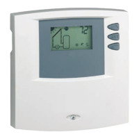
Only use the original temperature sensors (Pt1000)
that are approved for use with the controller.
Observe the following points:
Polarity of the sensor contacts is not important.
Do n
ot lay sensor cables close to 230 volt or 400
volt cables (minimum separation: 100 mm).
If inductive effects are expected, e.g. from heavy
current cables, overhead train cables, transformer
substations, radio and television devices, amateur
radi
o stations, microwave devices etc. , then the
sensor cables must be adequately shielded.
Sensor cables may be extended to a maximum
leng
th of 100 m.
For extension cables, select the following cable
cross sections:
0.75 mm
2
up to 50 m long
1.5 mm
2
up to 100 m long
Connect the cables in accordance with the terminal
plan.
Use only the Grundfos Direct Sensor
TM
VFS 1-12
that is approved for the controller.
-
-
-
-
-
-
-
-
-
-