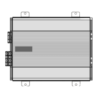
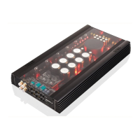
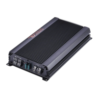
1 Amplifier positioning.
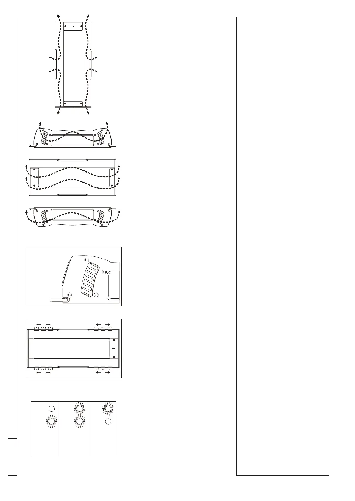
Do not place the amplifier under
moquettes or in spaces with surfaces in
contact with the heat-sink, since this
would prevent adequate heat exchange.
Also the direction of installation of the
amplifier is important like nearly object,
the forced cooling system (6 x 40mm
fans controlled by temperature and load)
create a air flux like showed in (fig. a), it’s
very important to leave free the input and
the output of that cooling circuitry, its
shape is specially designed for positioning
as shown in the (fig. b,c,) which
guarantees the best heat dissipation. The
(fig. d) position is absolutely to be
avoided, since it does not allow regular
functioning of the amplifier. STEG
amplifiers are, however, protected
against overheating; when the
protections are activated (85°C), the
amplifier stops working and starts again
only after the temperature of the heat-
sink goes down to a few degrees below
the protection threshold.
2 Fixing the amplifier.
To prevent damage to persons, the
amplifier or the vehicle, firmly fix the
amplifier in a safe place. The
amplifiers can be fitted in a
simple and efficient way . The four
feet provided are inserted along the heat-
sink groove and can be positioned at any
point along its length , and can thus
also be fitted onto surfaces where four
evenly-spaced holes cannot be made.
Once the foot positions have been
established, lock them by screwing down
the self-tapping screws provided.
3 Amplifier state (STATUS).
On the front panel of the amplifier are
two LEDs which indicate the amplifier
operating state
GREEN: on.
GREEN+RED: Muting state for
thermal cut-out or short-circuit on the
speaker line.
RED: Malfunctioning of the
amplifier which stops working to
prevent damage to the other system
components connected to the output.
Should the amplifier remain in this state,
it is advisable to contact a STEG
dealer.
master
stroke
(fig. a)
(fig.b)
(fig. a).
1
2
3
SAFESAFE
ONON
master stroke
msk 3000
SAFESAFE
ONON
master stroke
msk 3000
SAFESAFE
ONON
master stroke
msk 3000
SAFESAFE
ONON
1a1a
4a
1b
4b
1c
4c
1D2a
4D
2b
4E
3a
STATUSSTATUSSTATUS
1 2 3
SAFE SAFE SAFE
ON ON ON
4 (SUPPLY).
fig. a).
(fig. b) Positive (SUPPLY “+”).
I
(fig. c) (SUPPLY “-”).
(fig. d) (SUPPLY “ON”).
(fig. e) Exteral f
master stroke
Feeders
Always operate with the battery feeder
terminals disconnected. Once the final
position of the amplifier has been
established, cut off the excess cables and
insert them in the special terminal board
SUPPLY (
The power cable used must have an
adequate cross-section.
N.B. The greater the cross-section of the
cable, the higher the amplifier
performance. When running the power
cable it is recommended to avoid too
sharp curves, twists and passage through
sharp metal without the use of special
rubber pieces. Install a fuse as close as
possible to the battery to protect the
feeder. The fuse value must be greater
than the sum of the fuses required by the
other electronic parts connected to the
feeder.
Negative
The ground cable must have a cross-
section equal to or greater than the
power cable. The length must be the
minimum indispensable to reach a
metallic point on the vehicle body.
Remove the paint and thoroughly clean
the point at which the cable,
appropriately terminated with an eyelet
terminal, is to be connected. Tighten the
terminal well with a good-sized screw,
remembering to insert a washer to
prevent that the screw loosens with time.
If a hole needs to be made to connect the
eyelet terminal, first examine the
adjacent parts to prevent causing
damage to important parts of the
vehicle.
WARNING ! A poor-quality ground
contact means a drop in power and
worsening of the quality and noise of the
whole system.
Switching on
Connect a cable of about 1mm cross-
section to the source equipped with
ignition switch (dedicated output or
output for electric antenna). For the cable
passage from the source to the amplifier
use the same precautions as for the power
cable.
use (FUSE).
In case the fuse is blown, it must be
replaced with one of the same value. The
correct value of each
model fuse is indicated in the technical
characteristics in this manual.
pag. 18
pag. 19
TOP VIEW
FRONT VIEW
TOP VIEW
FRONT VIEW
TOP VIEW
FRONT VIEW


 To Next Page
 Loading...