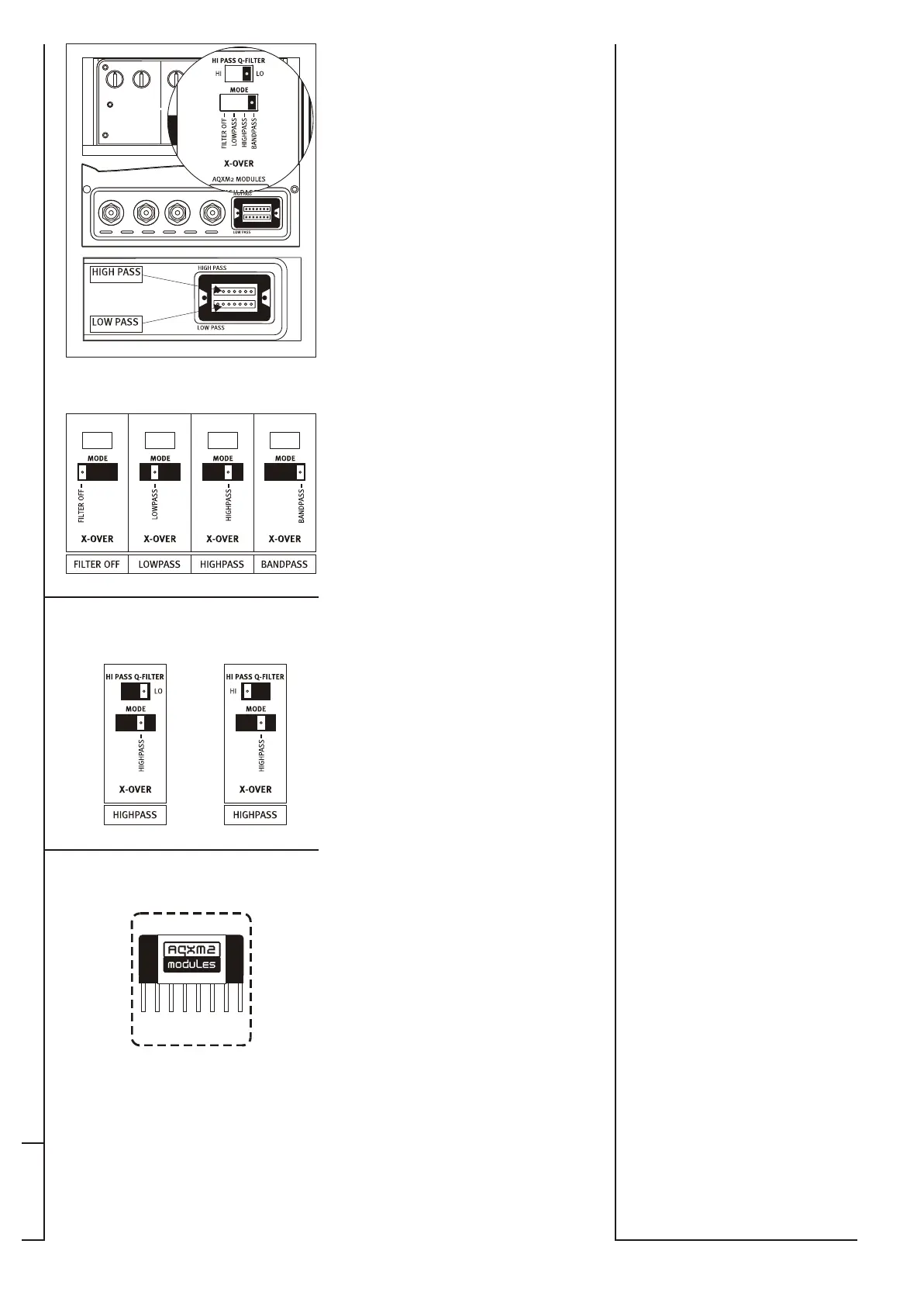
8 Electronic Crossover .
The master stroke amplifiers have
an internal electronic crossover, the
frequency cuts will be set by aqxm2
modules, inserting in the slots (HIGH
PASS e LOW PASS), located on the inout
side of the amplifier (fig. a). The cut-off
slope of the internal crossover is 12
dB/OCT.
To activate the electronic crossover act on
the (XOVER) switch and set it to the
preferred position: in (FILTER OFF) (fig.
b) position the pass band for the outlet is
in full range. This device makes it possible
to optimise the yield of the amplifier if
dedicated to reproduction of a specific
section of the audio range; for example if
it is required to limit the mechanical stress
of the woofers, the filter can be used in
high-pass mode (HIGH PASS) (fig.e) s a
subsonic filter by selecting a very low cut-
out frequency (e.g. 22 Hz). All
frequencies below the selected value are
filtered and the loudspeaker system fitted
begins to reproduce the set frequency.
On the contrary, if the filter is set in low-
pass mode (LOWPASS) (fig. c) , all
frequencies higher than the selected
value are filtered and the loudspeaker
system installed will begin to reproduce
the set frequency. The two types of filter
can be used simultaneously by
positioning the switch to the band-pass
position (BANDPASS) (fig. f) and limiting
the reproduction of the outlet range to
the range of frequencies included
between the two cut-out points.
If the high-pass filter is activated without
inserting the AQXM2 module in its
housing, in this case a subsonic filter is
obtained with cut-off at 22Hz.
9 Filter "Q"
The filter "Q" allows emphasizing the
sound response curve at the crossover
cut-off frequency point, when used in
(HIGH PASS) configuration (fig. 8e) .
The setting value can be two: 0,5 (LOW)
(fig. 9a) e 1 (HIGH) (fig. 9b).
10 AQXM2 Module.
The cut-off frequencies of the electronic
crossover are selectable with maximum
precision through insertion of the
optional AQXM2 module (fig. 10a)
available at STEG dealers in the values
indicated.
- Hz -
22without module,25,30,33,35,38,40,45,
50,55,60,65,70,75,80,85,90,95,100,
110,120,130,150,180,200,250,300,350,
400,450,500,600,700,800,900,1000,
1100,1200,1300,1400,1500,1800,2000,
2500,3000,3500,4000,4500,5000,
5500,6000,6500,7000,7500,8000,8500.
AQXM2
RUNNING WITH
MODULES
aqxm2 MODULES
aqxm2 MODULES
8a10a
8B
9A
8C
9B
8D 8E
GR.I.P.S.
GRound
I
mproved
P
ath System
P.R.H.E.S.S.
P
rimary Regulated
High Efficiency
S
upply System
Intermodulation distortion
0.0006
5
0.002
0.005
0.01
0.02
0.05
0.1
0.2
0.5
1
2
%
1 7002 5 10 20 50 100 200 500
W
Fast Fourier Transformer
-120
+0
-100
-80
-60
-40
-20
d
B
r
2k 20k4k 6k 8k 10k 12k 14k 16k 18k
Hz
-5
+5
-4
-3
-2
-1
+0
+1
+2
+3
+4
d
B
r
10 200k20 50 100 200 500 1k 2k 5k 10k 20k 50k 100k
Hz
Frequency Responce
0.0006
5
0.002
0.005
0.01
0.02
0.05
0.1
0.2
0.5
1
2
%
1 6002 5 10 20 50 100 200
W
Total Harmonic Distorsion
The exceptional constructive
characteristics and the “No compromise”
realization of this amplifier, are choices
confirmed by this measurement
diagrams realized in our laboratories by
Audio-Precision SistemOne equipments.
with 10,5 to 14,4 Volt power supply, @ 4
ohm load, harmonic distortion by power:
0,021% @ 465Watt
with 10,5 to 14,4 Volt power supply, @ 4
ohm load, frequency response at 1Watt
with 10,5 to 14,4 Volt power supply, @ 4
ohm load, intermodulation distortion by
power
with 10,5 to 14,4 Volt power supply, @ 4
ohm load, at 400 Watt nominal power
The measuraments was taken on a production sample and can be a little
variable by the smallest tollerance of the used components. The G.T. Trading
reserves the right to make any technical and aesthetic modifications to the
product without advisement.
pag. 22
pag. 23
 Loading...